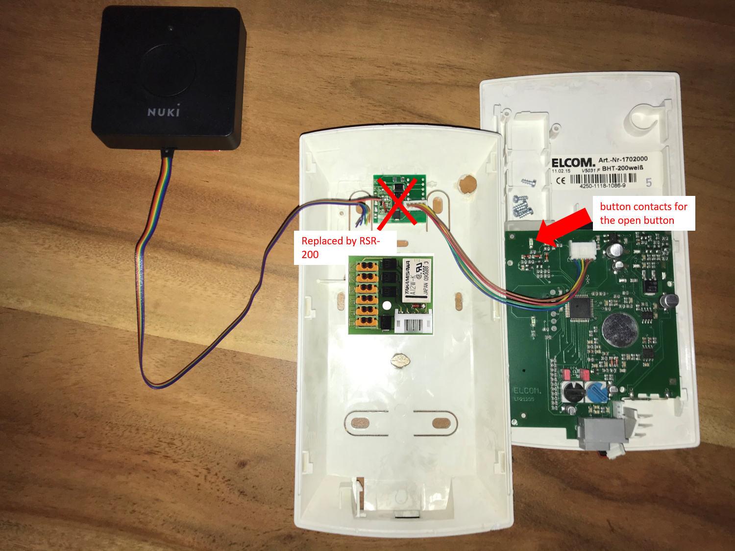
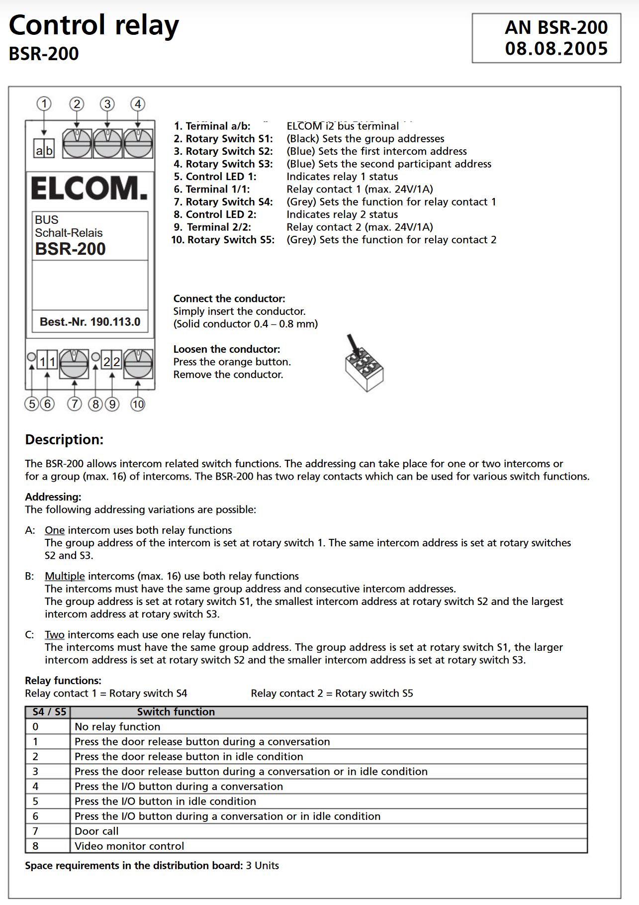
yes I replaced the orginal Board with the RSR-200 like described in your photo.
Then I used the 2 big pads of the button (on the backside of the circuit board where the red arrow in your photos points to. To solder cables to the pads, I removed the dark coating with a cutter knive.
For the wiring look at the section “Analogue intercoms” in this document:
You need yellow (ring detection), blue (door open signal) and purple (GND).
Between yellow and purple there’s an optocoupler in the Opener that detects incoming ring singals.
It seem to work with a wide voltage range, in a test the Opener detected 3V signals as well as 24V singals as a ring event.
Between blue and purle is a solid state relais that connects blue to GND when the Opener wants to open the door.
Be aware, that this means both functions use a shared GND (purple wire).
Luckily the button inputs on the intercom use pull-up resistors in combination with buttons that connect the input to GND when pressed.
Because of this, one of the button pads is the GND signal.
This allowed me to avoid additional power supplies and connecting other voltages to my Intercom system:
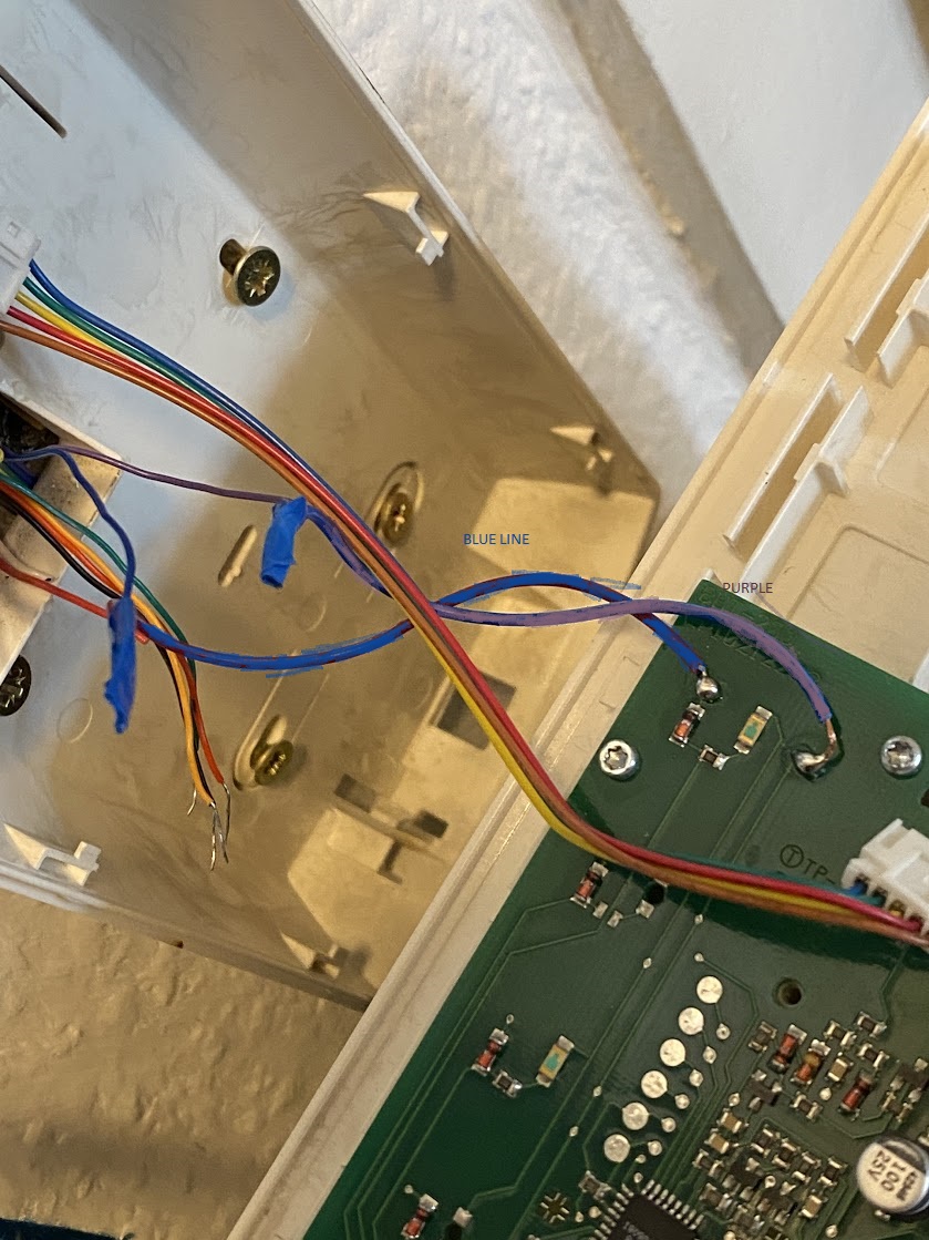
I use the BUS+ for the ring detection and switch it over the relais contact.
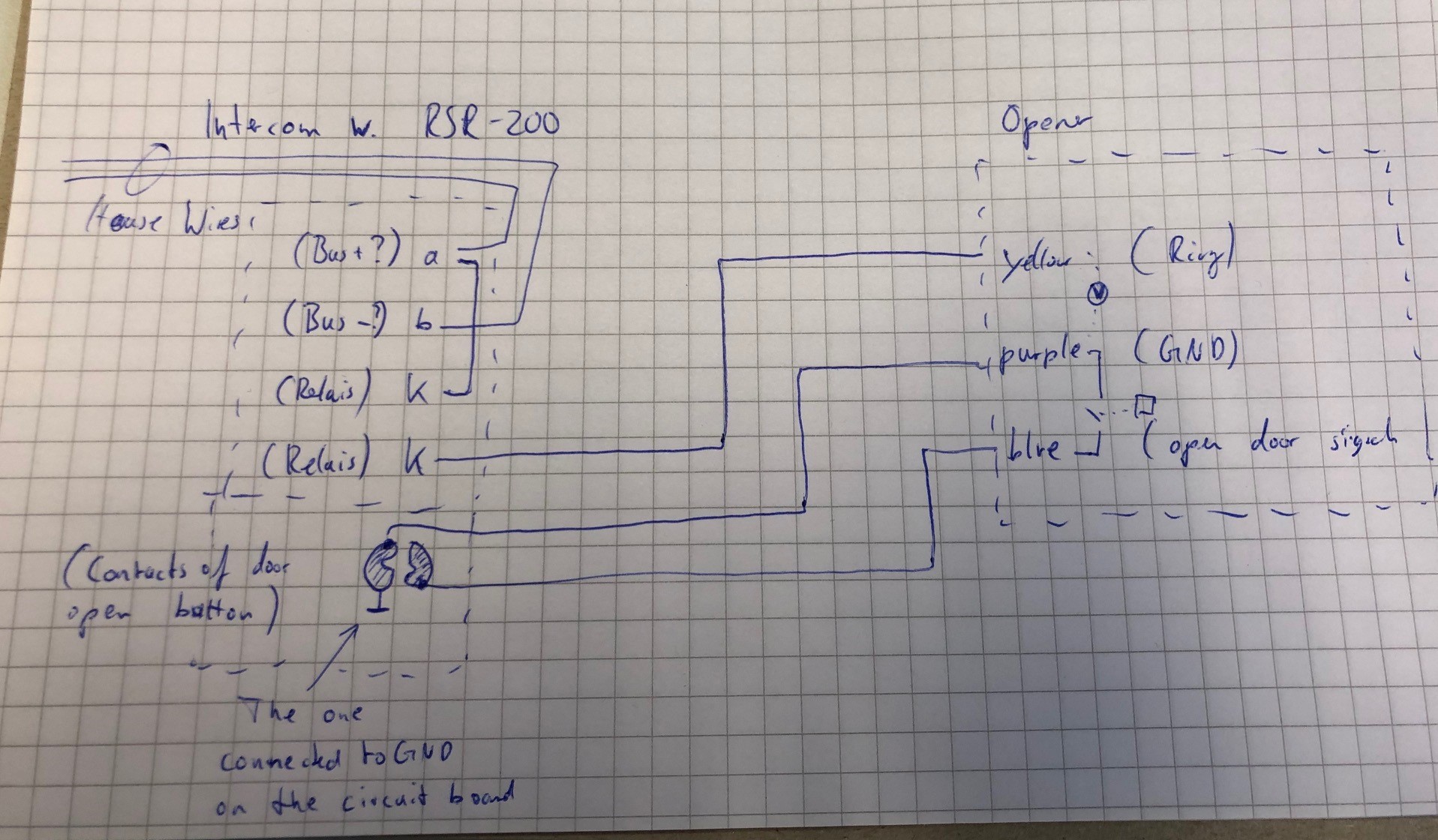
So the wiring looks like this:
One wire from BUS+ to one of the relay contact clamps of the RSR-200
Yellow wire from the Opener to the other relay contact clamp of the RSR-200
This results in an open input when noone rings, and 24V when a ring signal is active.
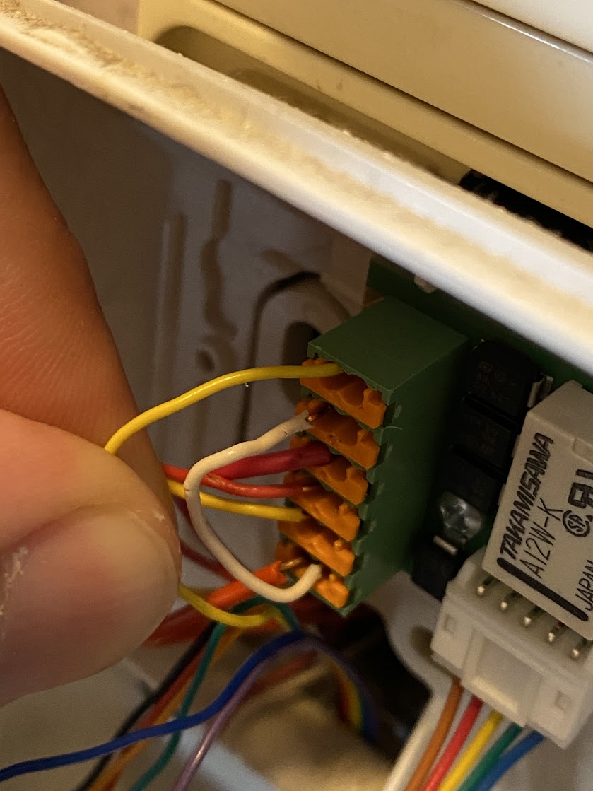
Purple wire from Opener to BUS- (GND)
Blue wire from opener to the button pad that is not GND.
That way, the Opener connects the button input of the intercom to GND,
just like the original button.
Then, in the app select Generic/Analogue for your intercom type.
In case you want to use your exisiting intercom station instead of a second one like I did:
Maybe you can see where the signal of the button input for “open door” is leading to on the circuit board and solder it on the other side of the circuit path.
Because if you solder it on the button pad, you might get problems with the original button.
Maybe this can also be solved by cutting some of the plastic of the top-part of the button where your wire is soldered…
I hope that helps, as Nuki doesn’t provide information about the internal connections of the opener on the website or in the app.
But the support team was very helpful when I asked by mail.
I can only use “Ring-to-Open” with our setup.
But in reality that isn’t a limitation for me so far.
My use cases are:
Enter the house with Ring-To-Open based on geofencing.
Enter the house with Ring-To-Open after activating Ring-To-Open with the button on the Opener when I leave the house just for a very short time (bringing out the garbage, …).
Detecting incoming ring signals and open the door without walking to the intercom.
This works fine at least with our iOS devices. I receive a notifcation about the ring event on my lockscreen and if I long-press/haptic-touch on it I get an button to open the door immediately (which works about 20-30 seconds on our intercom system after someone ringed).
So I didn’t miss the funcionality to open the door without ringing before so far…
Ok. Thanks. But if someone rings you need not to activate the voice communication before you can open the door, right? That is my problem. If someone rings I have to activate the video/audio communication before the door can be opened
thank you so much for the detailed explanation. Correct, I would use the intercom uniquely without any further added intercoms. In order to be on the safe side I have some additional questions which would need your confirmation, if possible .
“* One wire from BUS+ to one of the relay contact clamps of the RSR-200”
→ here you mean BUS+ coming from the house connection wiring needs to be plugged into “a” of the RSR-200 clamp, correct?
“* Yellow wire from the Opener to the other relay contact clamp of the RSR-200”
→ yellow will also be connected to the 2nd contact of “a” of the RSR-200?
"This results in an open input when noone rings, and 24V when a ring signal is active.
"*Purple wire from Opener to BUS- (GND) "
→ BUS- coming from the house connection wiring will go into “b” of the RSR-200 clamp and in addition the purple wire from the Opener will be connection to the second slot of “b” of the RSR-200, correct?
“* Blue wire from opener to the button pad that is not GND.”
→ will need to find the “positive” connector on the board.
One final question (at least for the moment) do I really need the RSR-200 since I could setup the wiring as stated already with the current circuit board?
The relay contact in the Opener is used to simulate the button press on the intercom.
As the purple wire is also used as GND signal for the ring detection, we connect it to the pad of the button that is connected to GND on the circuit board.
This way the Opener already has the GND signal to measure Voltage on it’s ring detection input (yellow wire).
Now we need a voltage that we can measure when the intercom is ringing.
The easiest way is, to use the supply voltage of the Intercom (BUS+ or “a”) and connect it over the Relais of the RSR-200 to the yellow wire.
That way the 24V of BUS+ will get connected to the yellow wire while it’s ringing, and will be disconnected after that.
Don’t know if it would be possible to do the same without the RSR-200 and connect the yellow wire to where the relay’s plus-pin is soldered on the RSR-200.
Maybe use a multimeter and check if you can measure a voltage between this pin and GND on the circuit board.
One more thing:
If you use your existing intercom uniquely the relay contact won’t get closed when you set your intercom to silent mode. That’s because the RSR-200 ist designed to be used for external audio signals which will be muted as well with the silent mode.
So the Opener won’t recognize the ring singal as long as the ring tone is disabled.
As I use a second intercom, I simply disconnected the speaker, but in your case you wouldn’t be able to talk to the person in front of your door with that setup.
So one idea if you want to try a little bit more complicated setup:
The relay on the RSR-200 has two 2-way contacts (two combined normally opened and normally closed contacts with one common pin in the middle)
The unused contacts aren’t wired to clamps on the small RSR-200 circuit board.
But you should be able to solder directly to the relay pins on the backside of the board.
Search for the datasheet of the relay and you will find the pin assignment.
You could disconnect the GND wire of the speaker and loop it over the second relay contact as normally closed connection.
That way the speaker should get disconnected when the doorbell rings, but should be re-connected when you start speaking to someone at the door.
Instead of the ring signal of the Intercom you could then use the ring signals of the Opener.
Another benefit here is, that you can configure it to not ring when “Ring-To-Open” is activated.
That way other people at home won’t get disturbed when you enter the house using Ring-To-Open.
@Kobaje, ok then your system has a different setup than ours.
I need to ring to be able to open the door, but I don’t need to start a conversation with the person in front of the door.
I can immediately press “open door” on the intercom.
If you can’t change that, your setup would need a more complicated solution, as you might have to simulate 2 button press events with a short delay.
In case you can use a second intercom as I do in a place with an power outlet and where you can hide the wiring in a little box this might still be possible.
An idea would be to use 2 relays, one of them with the possibility to set a delay for closing the contact (.
Then connect the A1 pins of both to an external voltage (maybe use 5V relays, so you can use a little USB power supply. The A2 pins get connected to the blue cable of the Opener.
As last step connect GND of this power supply to the purple wire, where you already connected the GND of the intercom.
That way, the opener should activate both buttons, the speak-button immediately, the open-button a little bit delayed.
Hey!
Awesome information - thank you so much!
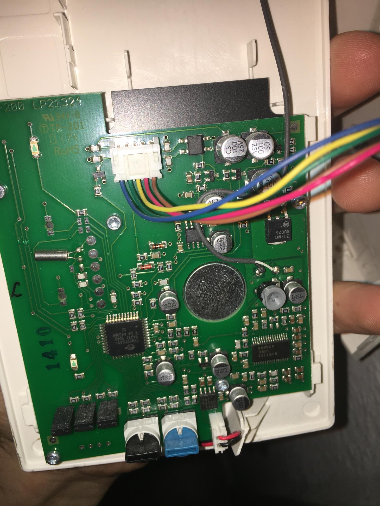
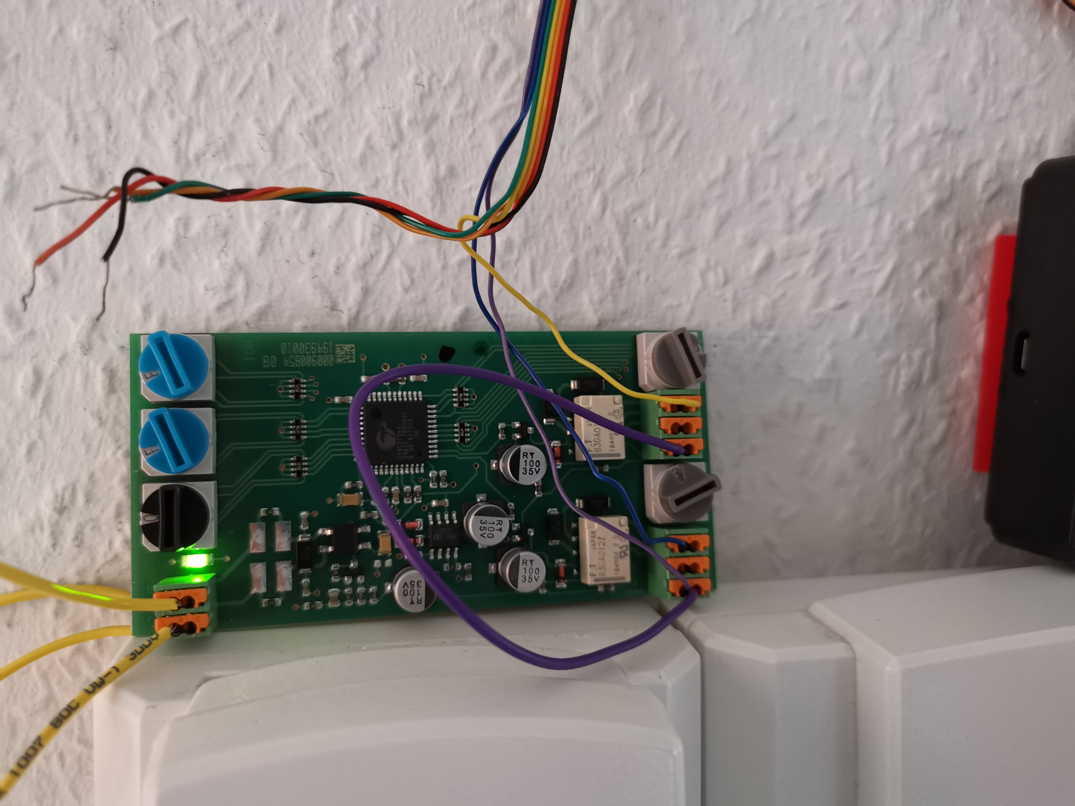
Any chance you could point out the Button in this picture of the BFT-200? The one that looks most similar to the one above is the Speaker, not the Open-Button.
Also the idea with the speaker sounds sweet but I think that’s just a little bit too much for someone like me that doesn’t understand the setup
sadly what I read in this topic is a bit above my skill set so I‘ll just ask bluntly. Is this the right place to look for answers that might help with getting the opener working with my Elcom BVF-210 WS? It is the Intercom with video and touch keys. As I read similar descriptions I thought this might be the same thing.
I am hoping there is a solution coming up soon for those intercoms.
Hi Tobias, I also have the Elcom BFT 200 and was reading about an installation with an additional board RSR-200. Unfortunately I am just a normal consumer and reading to the instructions isn’t that easy to follow. Would it be possible to get more pictures for every step, so I can follow the instructions and do the installation myself. I am very handy, but no professional. Would be really great to get your support. Thanks in advance, you would be a big help, Felix
Things needed:
BSR-200 Module as stated by Tobias and also Florian, thank you guys!
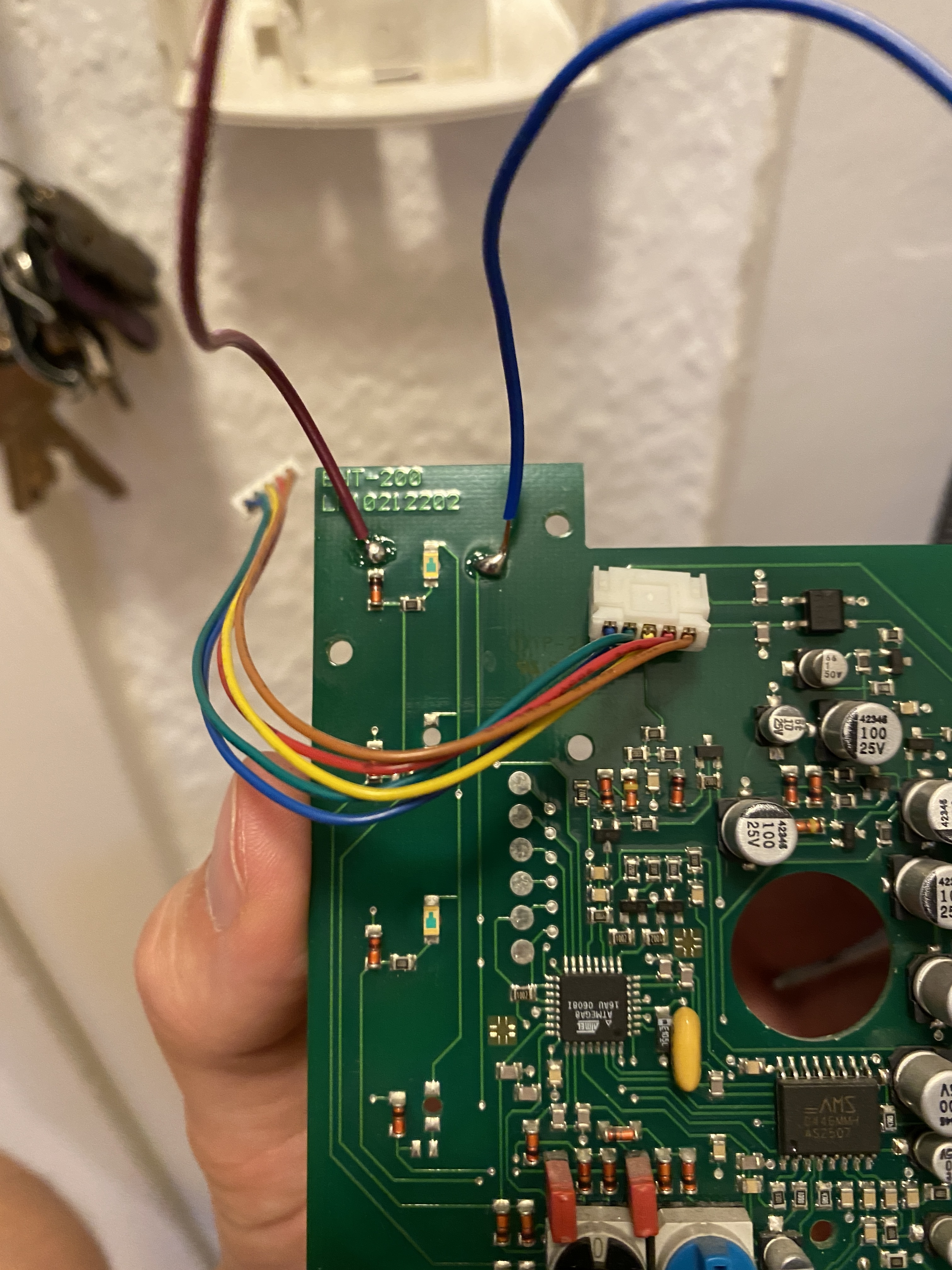
I soldered 2 cables on the front connections of the board (Blue and Purple Cable) you don’t need to solder it on the backside with the black coating.
Ring detection yellow to BUS+ as already mentioned but make sure to follow the procedure in the app precisely! (Ring - door not open - Ring etc. To let the Nuki learn the different voltages)
I am writing on my phone and edit this entry tomorrow with some proper images
And here my working quick and easy cable setup - please follow the colors from the NUKI side - I tried my best on Paint.
So advice:
SOlder to the fronside / Attach with some glue or whatever, you can use this contact here and it will work like a charm, if you are using a RSR-200 Module
I had an small typo, since I don’t have a BSR-200 installed. I am using an RSR-200 only, which is about 20-30€ and far cheaper than an BSR-200 with its price of 90€+++.
Maybe you can use the BSR-200, but the ring detection has to work properly, maybe you can skip the activation mode in that case. But I won’t be able to test it, I am living in a rented flat where I wont be upgrading the house ringsystems
Down here a bit less successful. I did connect the BSR200 (which is a 2 way relay) and set it up that way:
a and b from i2 going both to my BVM-100 and the BSR 200. From the BSR200, I connect (contact 1) NO with blue wire, Common with GRD (purple) with the setting “pressing door release button on idle and during conversation state”. Second connector in “door call mode” with yellow cable on NO and GRD on Common (contact 2).
When someone rings I can see voltage on the second connector light (contact 2 active), and when I press the open door button I can see voltage on the first connector (contact 1 active).
I did try to set up the opener in generic/analog but no chance, I don’t even see the status light (so contact 1 ain’t active) on on the BSR200 when the Opener is supposed to send the opening voltage.