Thank u/u too- waiting 4 response…
Hey Georg. What’s the thing you need to do to get ring detection from the speaker line?
Have there been any new developments on “officially” supporting the SKS 2- and 6-wire systems without the analogue workaround? It looks to me that technically only an appropriate wiring adapter (Nuki to through-holes?) would need to be made and the rest should be able to be handled in software? sks is super prevalent in Berlin and other cities
Ok - sounds like a silly question - but my il vertro video looks completely different from the one @Panda mentioned here. I have even trouble finding ground - not even talking about finding the “opener” wire… any clue?
And @Georg_S what do I have to do to get my opener set “free”
![]()
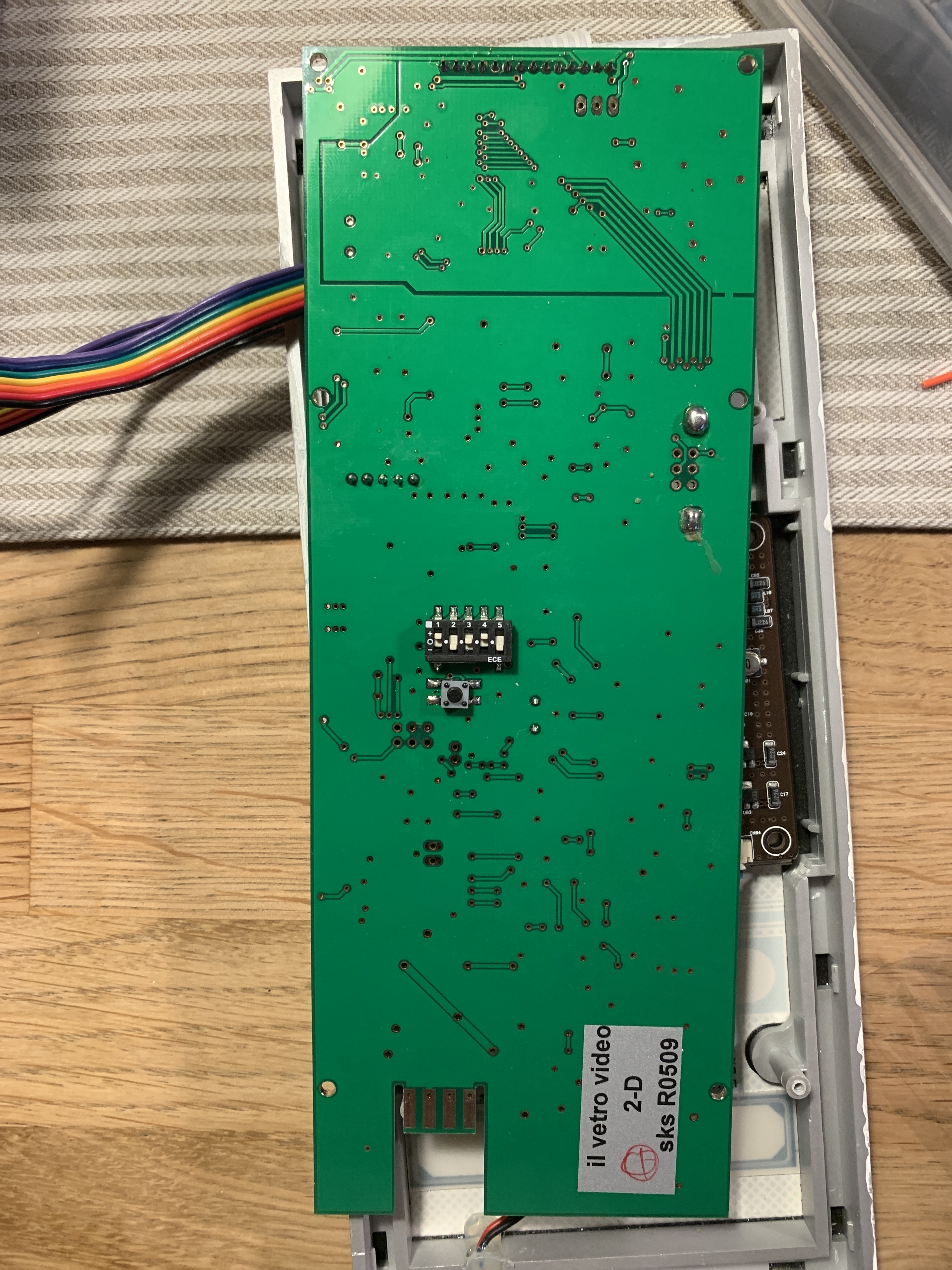
And one additional question: i think I found some GND to use - now the tricky part to figure out the opener - it’s a capacitive touch - so what I tried:
Connected voltmeter to gnd and check for voltage on the pins - there was one pin that jumped from 0.6 to 2 V after pushing the opener - but it did the same if the other buttons are being pushed. Any idea how to find the right connection point?
Is it the same with yours @Panda that there is voltage if you push the other buttons? Do I need to ring the bell downstairs to figure out the right pin? (Because of the “open only after ringing” function of Sks?)
It is the 2 Cable il vetro by the way
Check if you get an beep sound if you press the opener button. If not, you will need to ring your door before measuring which pin the opener pin is.
For me, I just measured each pin of the connectors coming from the touchpanel while pushing the button just like you. On one of the pins, you should clearly see a change between 5V and 0V. That is the one to go for. The panel is capacitive touch, but the detection circuit sits in the touchpanel part, so the connector has very clean signals just like an regular button.
Thanks @Panda - ok I think I might figured one … it is at 120 mV and when I push the opener it jumps to 5 V - so far so good.
But still can’t get it to work. I connect all cables - but can’t finish the configuration - it always tells me “configuration failed”.
The bell rings - and ring suppression is working - but it seems Nuki is not registering the input of the ring. The detection is from pcb straight - so no messed polarity.
One strange thing: ring suppression turns down the volume of the ring to almost nothing - but you can still hear it - if turned of it is the full volume.
Is it necessary for @Georg_S to change sth before it even can work?
If ring supression works then Nuki has correctly detected the ring. If not ring supression would not kick in. Also, you can check if it works correct by enabling and disabling it in your settings. If both work as intended, ring detection is wired correctly. Opening happens after the end of ring has been reached. Check if all your wires except orange are connected correctly similar to: SKS HT4600 or BS2012, compatible Nuki Opener - #53 by DominikZ
did anyone try this on the HTV4600 so far and has the wiring figured out?
I don’t get it - i checked the wiring several times - even tried it with ground of the speaker.
What’s working:
- ringing my doorbell —> very low volume sound of our „original“ bell and „ring sound“ of the Nuki opener if set to „ring suppression“
What’s not working:
Everything else ![]() .
.
I can’t get the configuration finished - I always get „Configuration failed“ after the part in the configuration where one should ring the bell downstairs (in German for the required „Freischaltung“) in the opener app.
Do I need anything from @Georg_S (not responding in weeks unfortunately- is he still here?) so that it can work? I appreciate any help at all! Is there any one else Form the @moderators / @Team instead of @Georg_S who can help out instead?
And @Panda sorry for bothering you again - can you tell if the pin you choose for opening has an connection to one of 14 pin connectors (connecting the PCB with the Touch - and if so wich one? (Counter e.g. in your picture from the left) would assume number 7
or 8? Do they have a voltage if no button is pressed (mine all show 3.x V instead of one Ground and one with 0.x - but none of theme change while pushing (or my voltmeter is to slow)
The chosen pin has a direct connection to the pin header between main PCB and touch panel. I don‘t know which one it was anymore. There was a voltage switch on mine when I pushed the button. If I remember correctly the signal was pulled down when the button is pushed, but I am not 100% sure anymore as it was quite a while ago.
Thanks @Panda - still no luck - I checked every of the 14 pins - one is dropping if the “camera” button is pressed - but none of them is dropping while pushing the open/key button (despite it does make the “beep” sound).
Is it to much to ask if you could peek into yours to tell me which of the 14 pin headers it is? I doubt that they change the connection numbering of the touchpad between the 2 and 6-Line bus? I really have no other idea how to find the right one… I know the belonging points on the pcb to the 14 pins of the touch - but just can’t figure out which pin is the open button.
I really would appreciate it! Thanks in advance …
Hey @Lionstark were you able to connect your htv4600? I have one myself and currently experimenting with no luck so far ![]()
@Panda sorry for bothering here as well with a dummy question: are you using the wires directly connecting with the pcb (i mean the ones “coming out of the wall”). or are you using other wires on pcb somewhere?
I am wiring custom wires to the PCB. Using the wires out of the wall will not work.
1 Like
Hallo Georg,
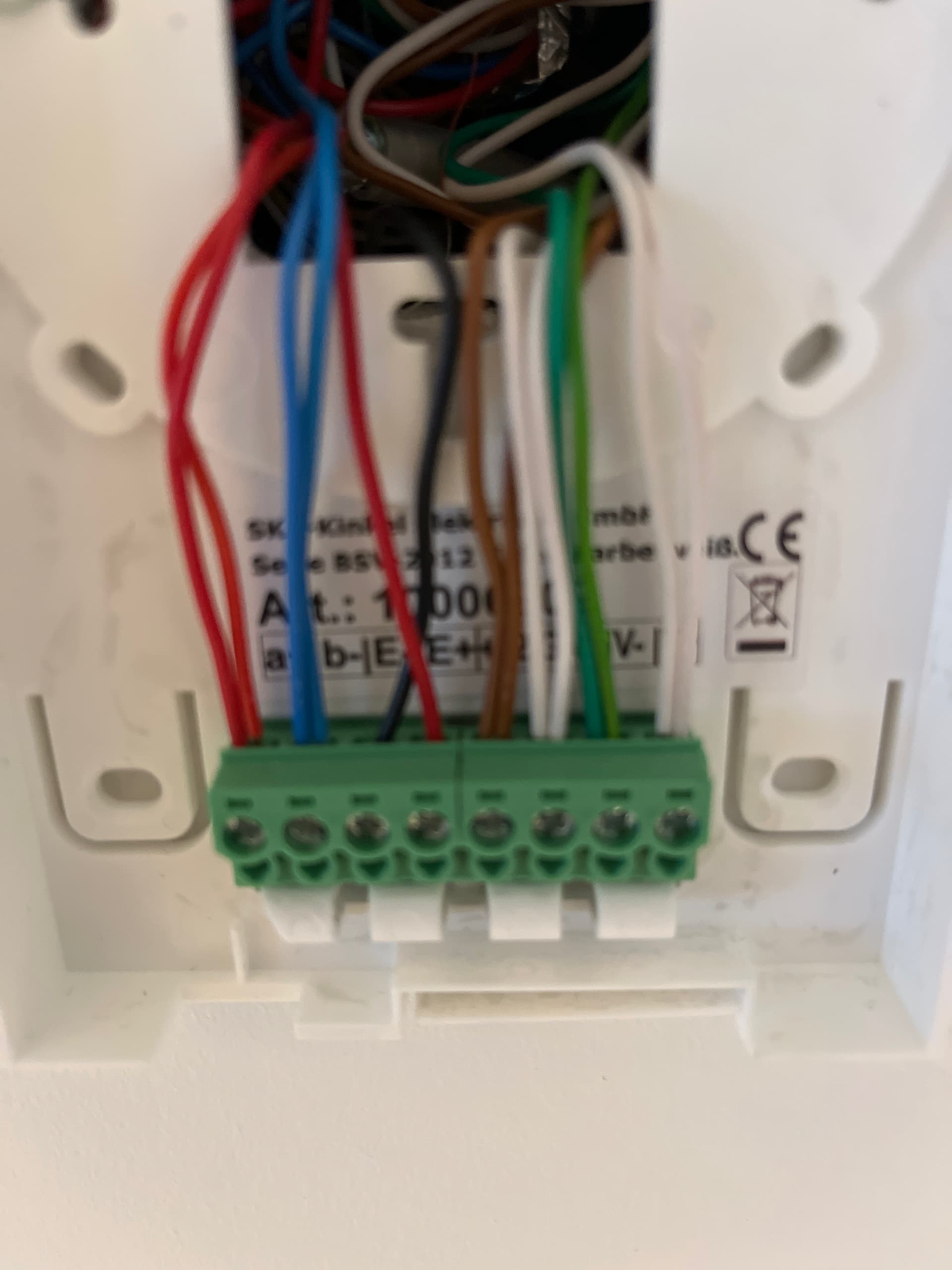
I moved into a new flat. Here is the BS2012 from SKS installed.
I don’t need the ring suppression. Is there a chance that I got it working without suppression and or soldering?
Thx for a reply…
Best regards from HH Germany.
For me the option without suppressing the doorbell would be ok.
So if anybody can tell me how to connect the opener I would appreciate it. ![]()
@Panda hey, if you have some spare time to look at this, amybe you can help me ![]() i have a sks ht 4500/3, for which there is no direct solution how to connect it to the opener at this point of time. So i tried to map your clever solution for the sks bus problem onto my device.
i have a sks ht 4500/3, for which there is no direct solution how to connect it to the opener at this point of time. So i tried to map your clever solution for the sks bus problem onto my device.
I dont have a multimeter what makes things a bit harder, but shouldnt be necessary as i have hard buttons.
in the picture you see where i soldered gnd and blue/unlock wire.
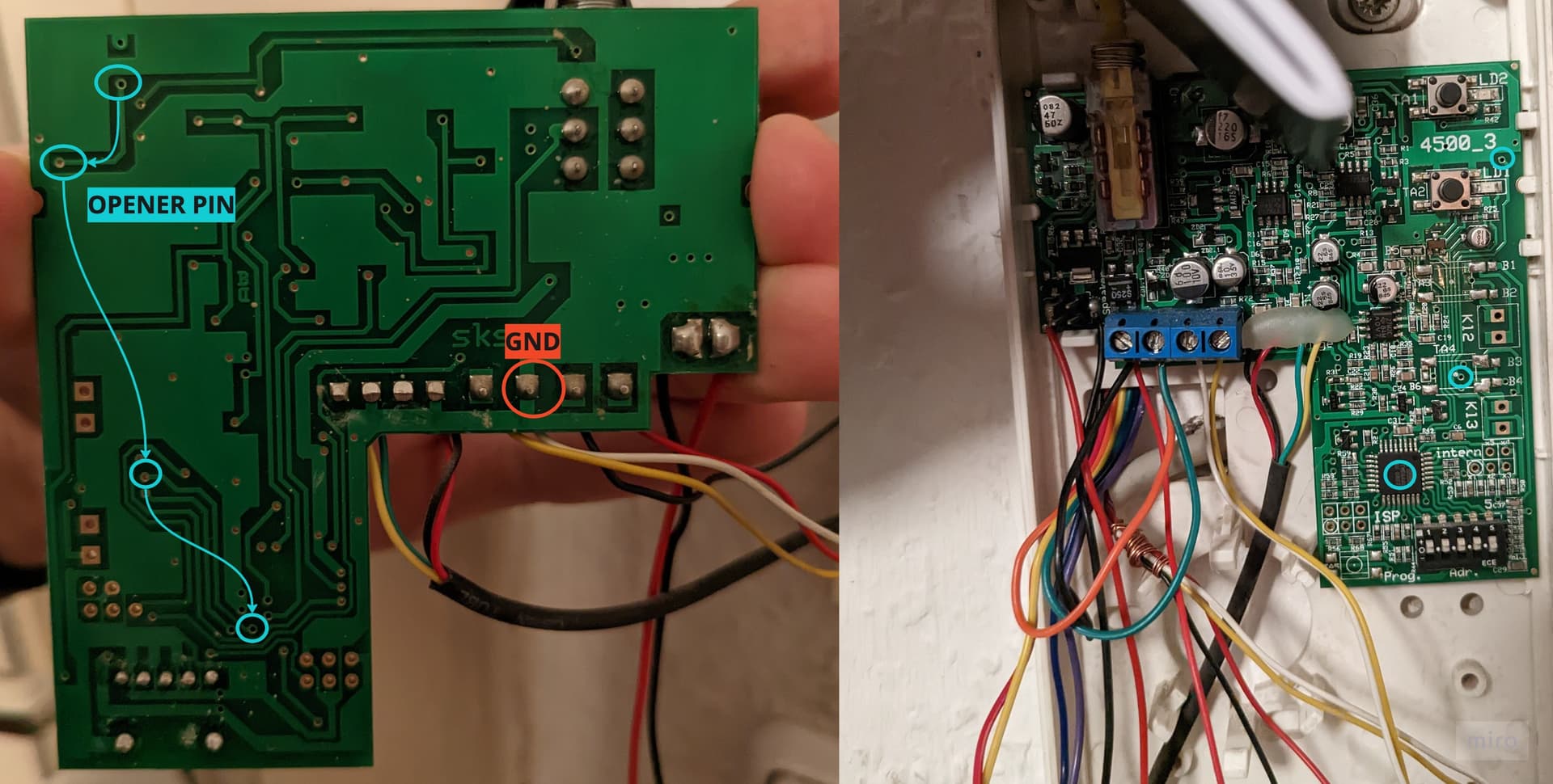
others are between speaker aso.
unfortunately this does not work, opener cant open my door.
what is wrong? i see that the unlock button seems to bring the pin going to the chip to ground? isnt that a bit odd?
can you help me figure this out?
I can’t see how black/purple are connected to ground. Also I can’t see the blue connected to anything.