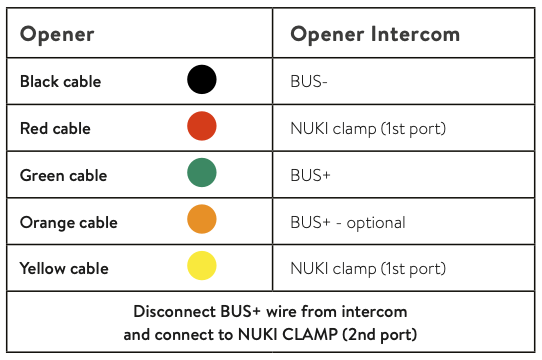
Is there a anyone out there who could help me understand how I should connect the Opener to my Aiphone GT-1M3-L?
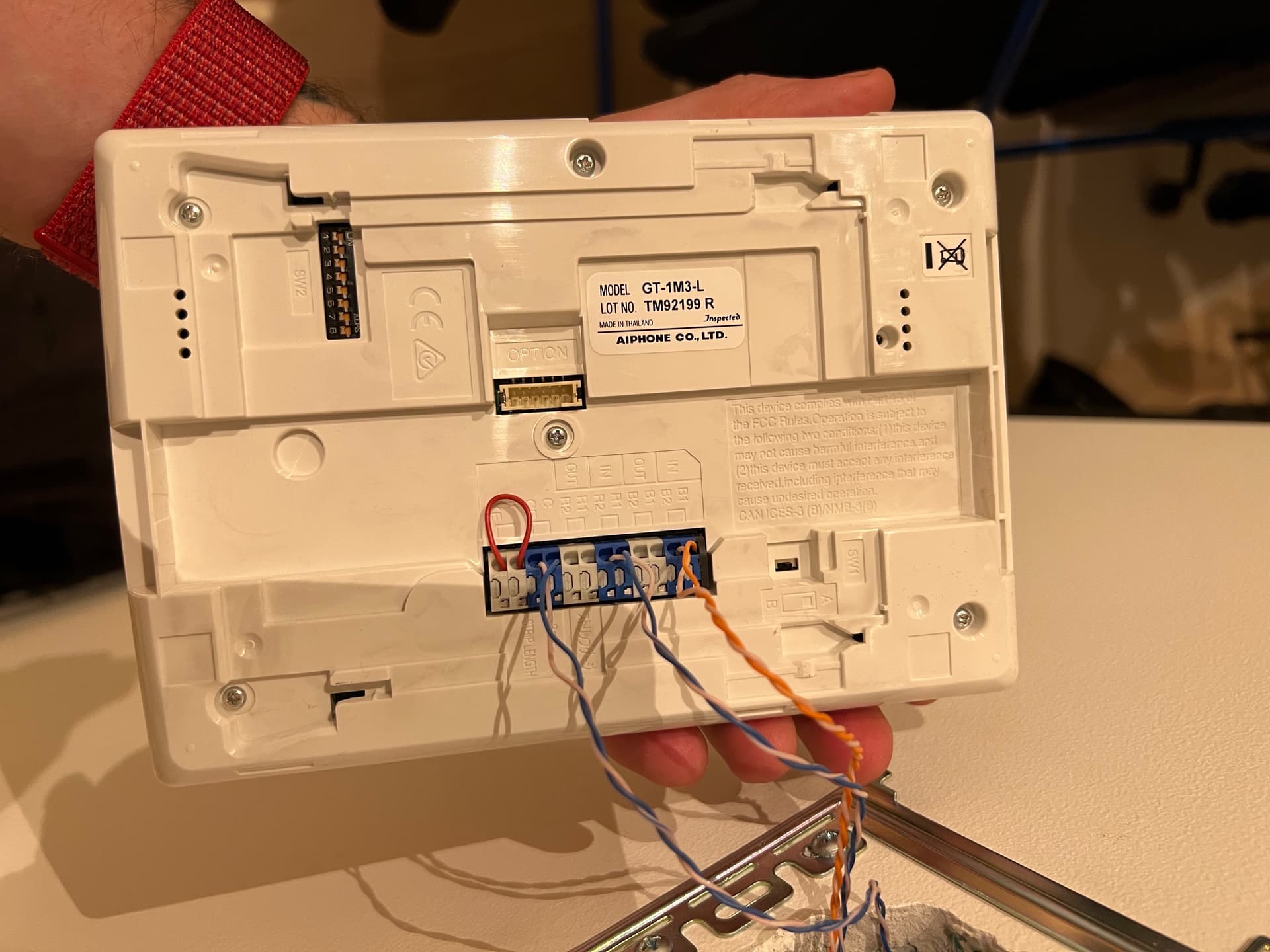
I have figured out that it is a BUS intercom. The Nuki generic installation guide however refers to two ports, BUS- & BUS+, which doesn’t exist on my intercom (See image below). It has B1,B2 (Video) & R1,R2 (Audio). I’m trying to figure out which ports on mine that corresponds to BUS- & BUS+ and I would very much appreciate any help.
Hi! Audio R1/R2 are the ones you need, I think! But you have out channels, so when the opener can recognise and imitate the signals, you can use this outputs, and just when you want ring suppression, you would have to connect one wire to in, for sending back the ring signal.
So should I follow the HowToGuide for BUS intercom where BUS- = R1 and and BUS+ = R2?
As long as I won’t shortcut anything by connecting the wrong wires, I’m not afraid to test.
I guess I can detach one of R1/R2 and ring the bell to see if I have disabled the loudspeaker? And that’s where the red and orange cable should go? And then the black in the other one?
I tried detaching the cable in R1 and R2 individually, but when either was detached, the intercom didn’t work at all. I reattached the cables as before.
Now I tried to cable it according to the wiring diagram for a Generic BUS intercom where R1 = B+ and R2 = B-. No luck.
Then I tried to reverse cables for R1 & R2, and then I at least got an instant error in the app, so I reversed it back.
Hi! I would try the out channels, because then you can’t mess something up with the working intercom wiring, when trying different wirings with the opener! And it’s very important, that you disconnect the wires plug from the opener when wiring, and set back the opener to factory settings, before plug back in the wires plug!
Do you mean the IN/OUT? I think they are meant for serial connections (daisy chaining). This is set up with wires directly to a central, so I’m in doubt that the OUT ports will work as it probably need new configuration in the central.
I am disconnecting the plug from the Opener when wiring, yes
Which type of wiring should I use to include the out channels? Analog/BUS/Other?
And there are no cables in the out channel, so should I ignore the clamp? Should I use IN for some cables and OUT for some cables?
Thanks for taking time out of your day to help me =)
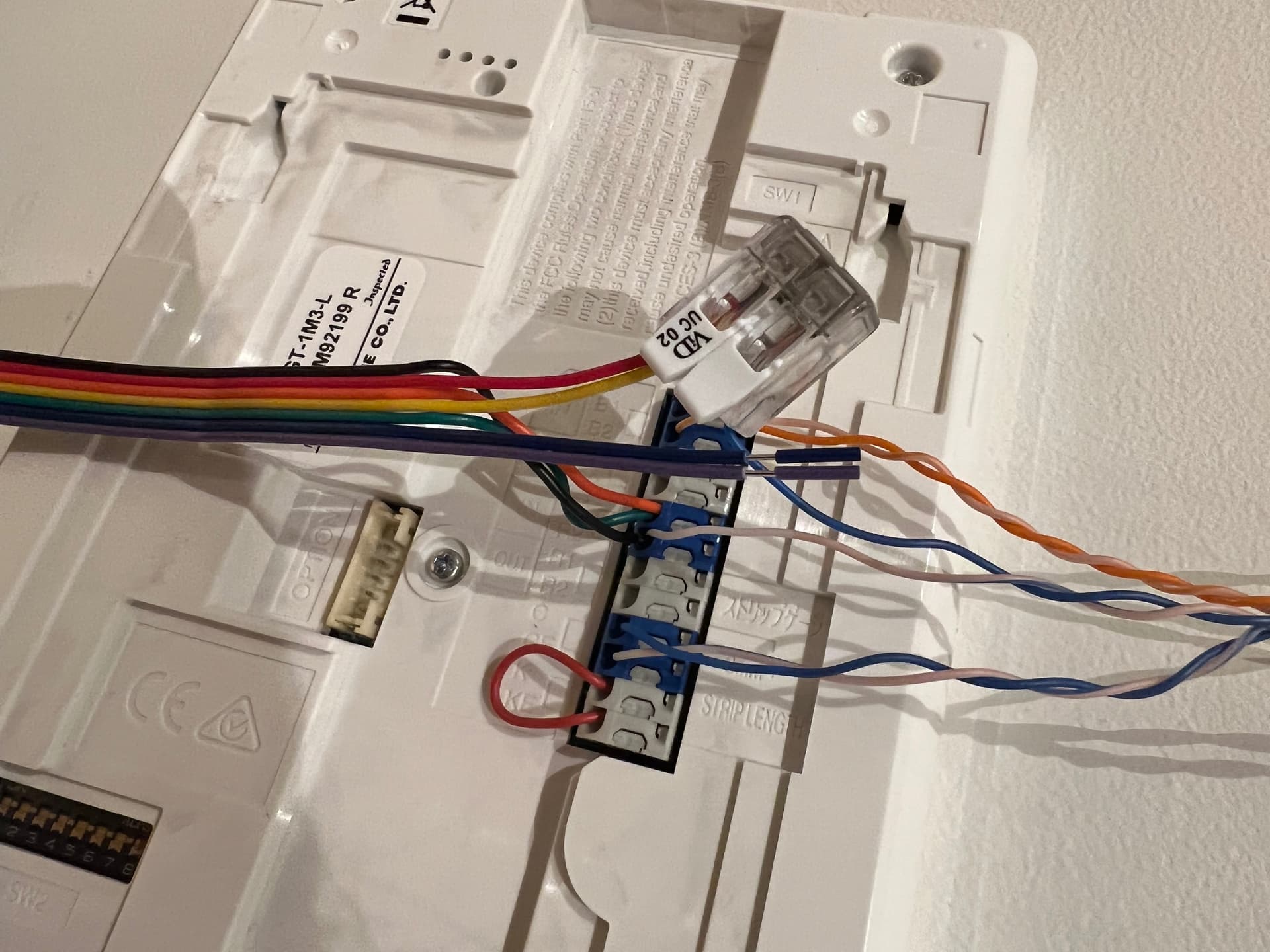
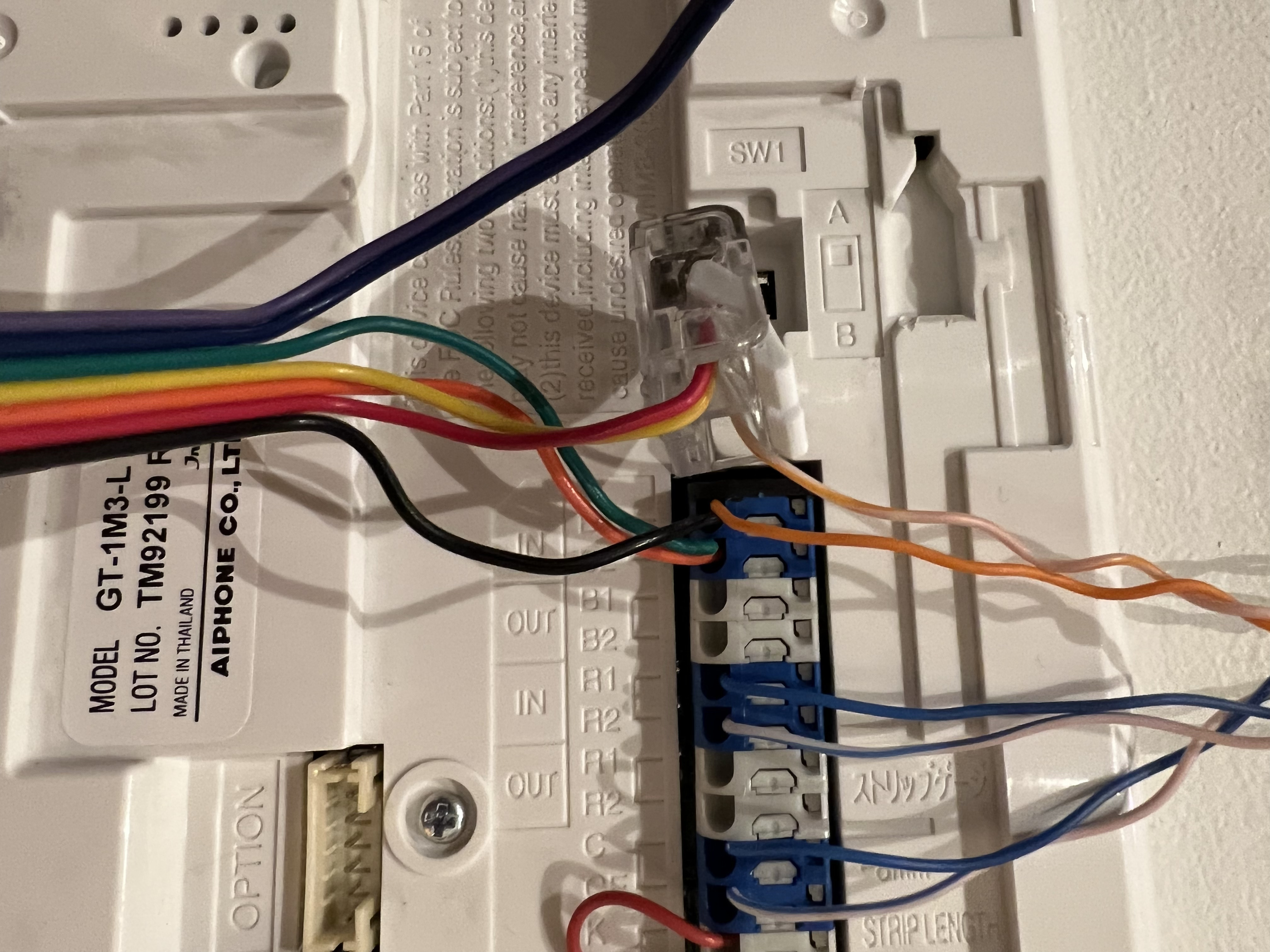
Unfortunately, it didn’t work. I tried both with B1=+ & B2=- and vice versa, as you can see from the pictures. Both get the error “The installation of your intercom system
does not comply with the standard” in the app.
I don’t get this error on either R1=+ or C=+ (I tested that too).
Ok! Its a tricky thing this intercom! Please try this just for testing, - remove at first all opener wires and remake the original wiring of the intercom. Then Red&yellow in clamp and a short wire from the clamp to CE, now Green&Orange to R1 and Black to R2, and try again!
No luck with that either. Got the same error with red & yellow in C and CE.
I also tried to swap R&Y with G&O, so R&Y → R1 & G&O → C (also tried G&O → CE) This did not give me the error, but it didn’t work either.
Same result as when I tried with R1 and R2. I get to the part where I’m asked to step outside and ring the bell. But it just doesn’t get or recognise the bell signal.