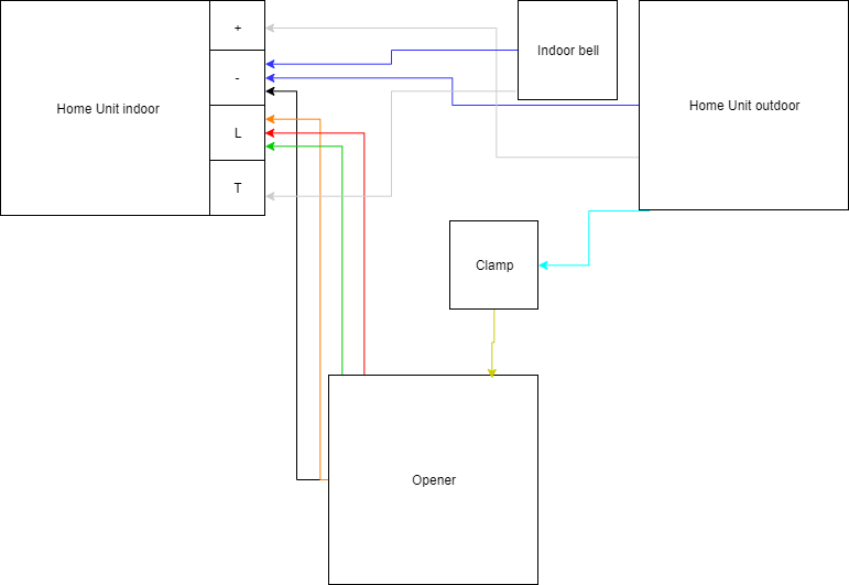
Ok, If I understand bus “+” of digital intercom is “L” and you don’t use the Nuki Clamp? The red one from Opener goes to Clamp and then “L” of intercom?. And the yellow one from Opener to the Clamp too?.
I did the wiring like stated in the PDF “Enhanced setup with doorbell suppression”. Give me about 15 minutes and I’ll give more pictures.
This setup is with indoor bell:
Here are some more pictures:
The clamp:
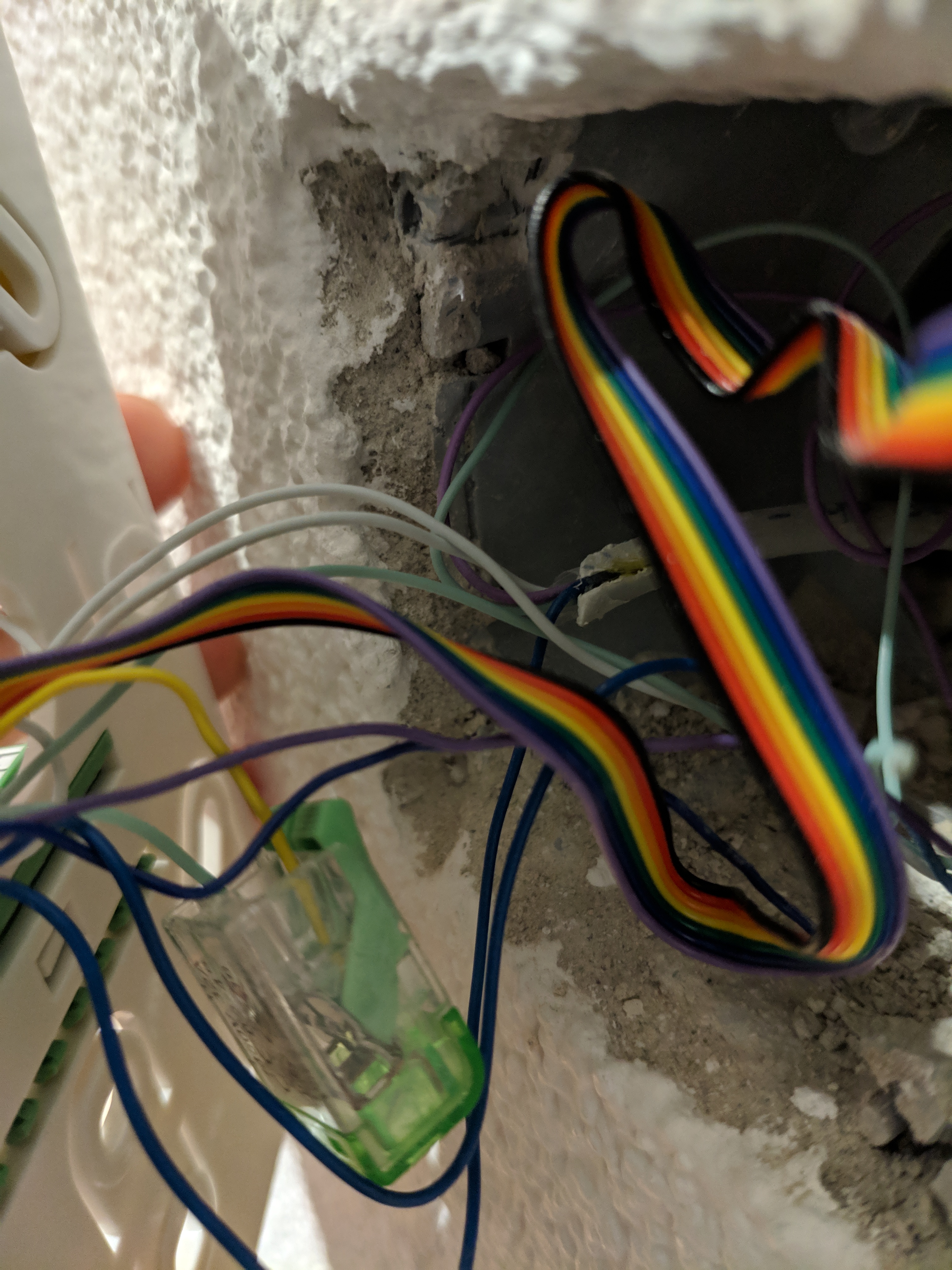
Two incomings (indoor and outdoor):
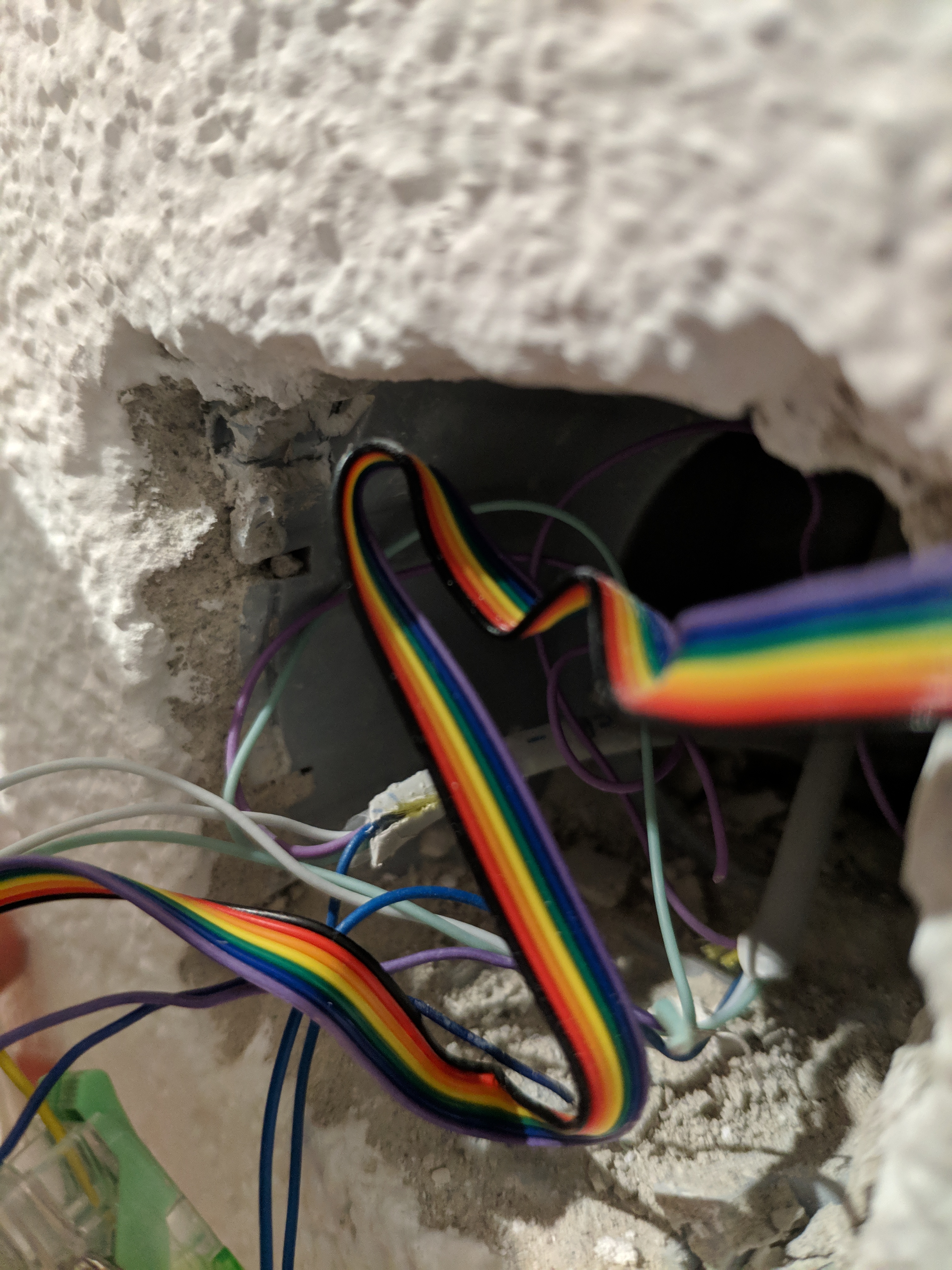
Lila is never connected, the turquoise one from outdoor is connected to the clamp.

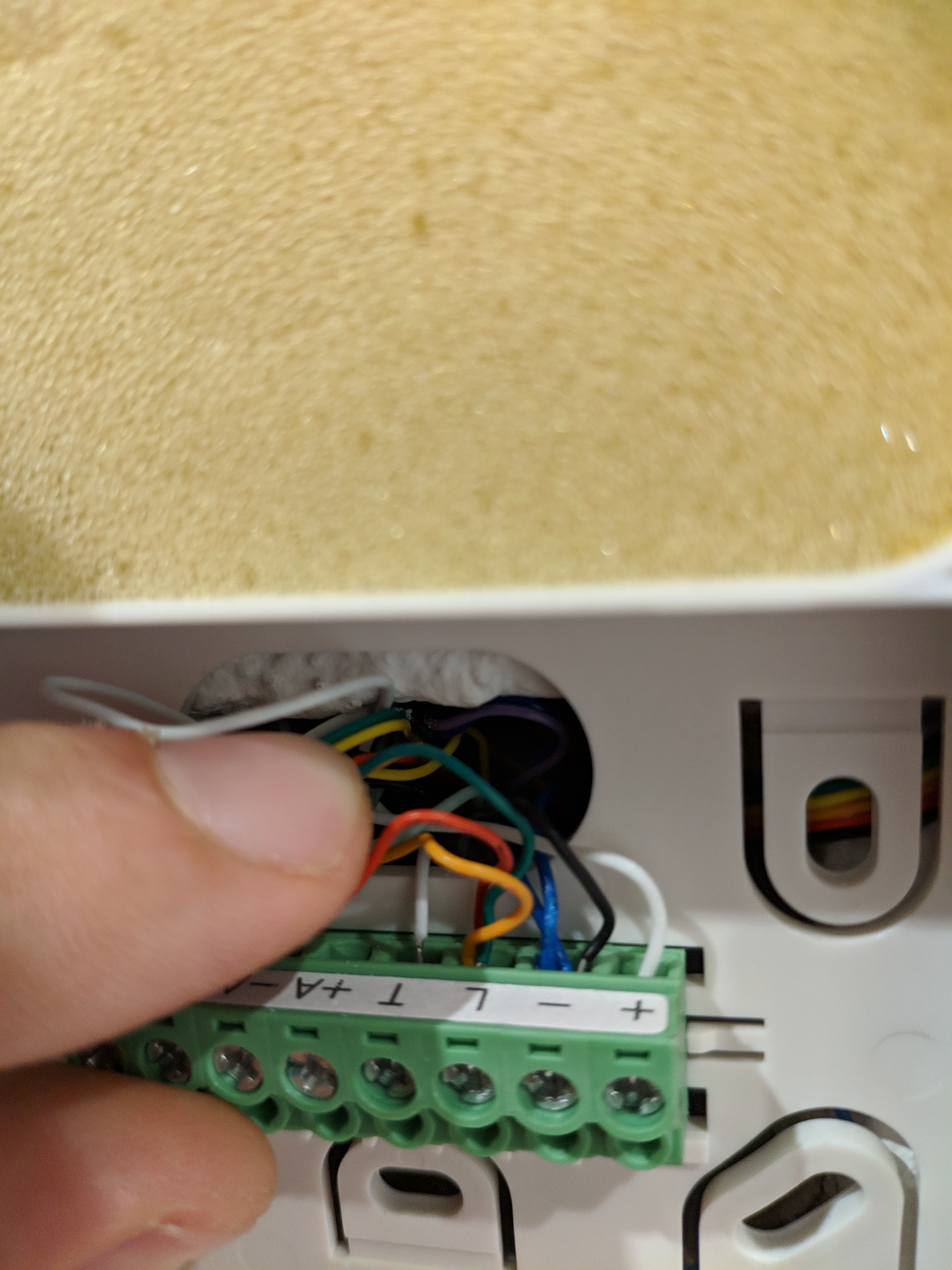
At the end you have following external cables connected: 2x blue, 2x white (T is indoor bell), all other cables are from the opener.
Edit: The turquoise is the data cable, this is the one we sniff later on in the setup. You have to ring the bell and so on, the app will guide you. Just follow the instructions and answer correctly! It can be confusing to follow the app but it is getting the things right. Important: My door only opens if the bell is rang! Else nothing is happening.
Edit 2:
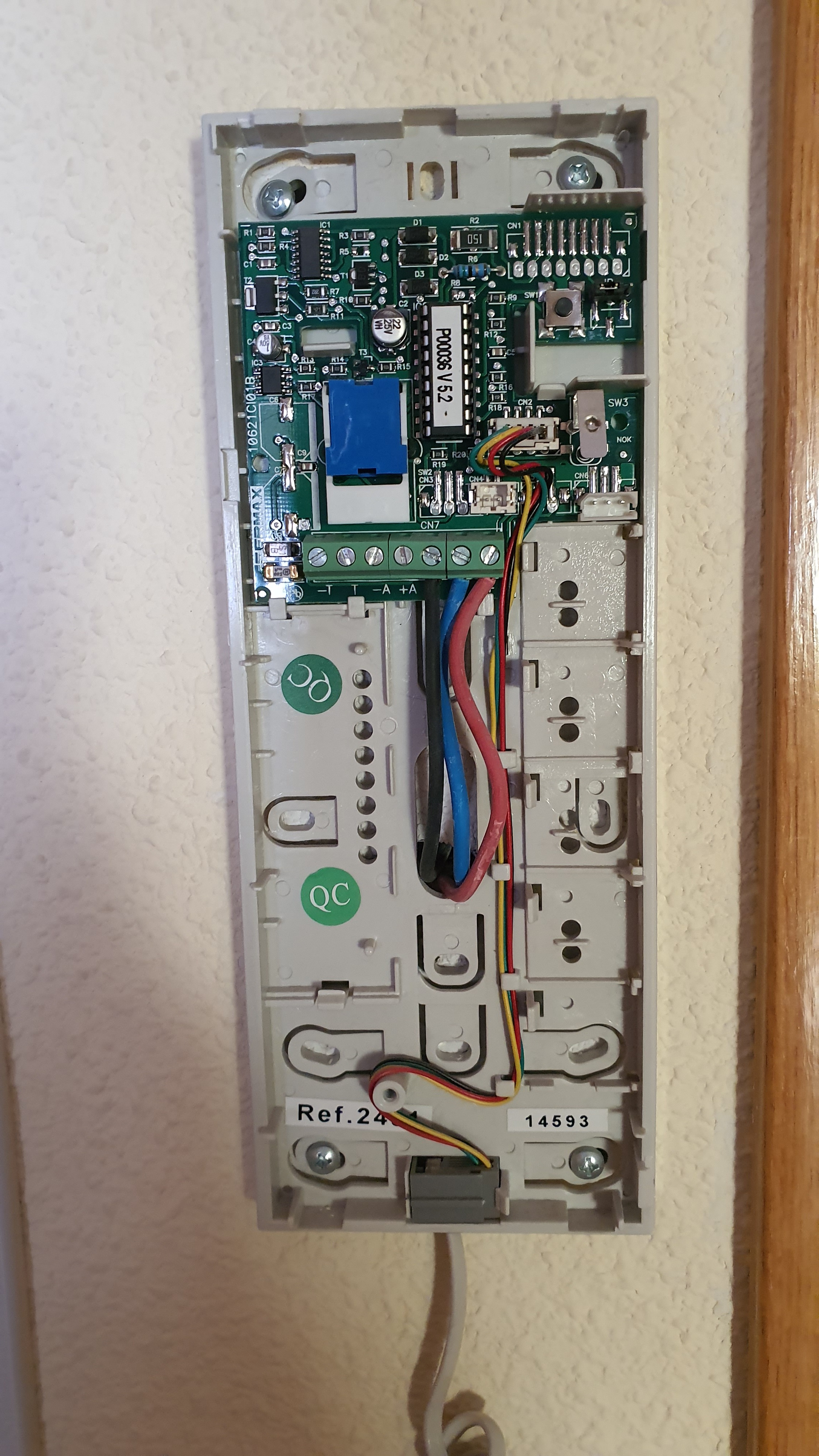
This is the wiring before I changed anything:
Ok. Understand now. I took only the “L” wire from outside to the Clamp and goes to Opener. From the opener Connect wires to “L” and “-”. Thank you for your work and patient.
Yep, exactly! Good luck getting it up and running. ![]()
Hello Manuel
Can you help me how to connect the opener to my phone scheme ?, I think I tried everything now and it doesn’t work
Thank you
Can you get a picture of the labeling of the connector? If you know the model, you can get the pdf online from the vendor, maybe we find out more with it.
If wiring is correct:
Follow the setup with generic and bus (generic). Ring your door bell, press open and so on like stated in the setup. If your door won’t open, its ok. Maybe it will only open when the bell is rang, the setup will recognize it after a few tries.
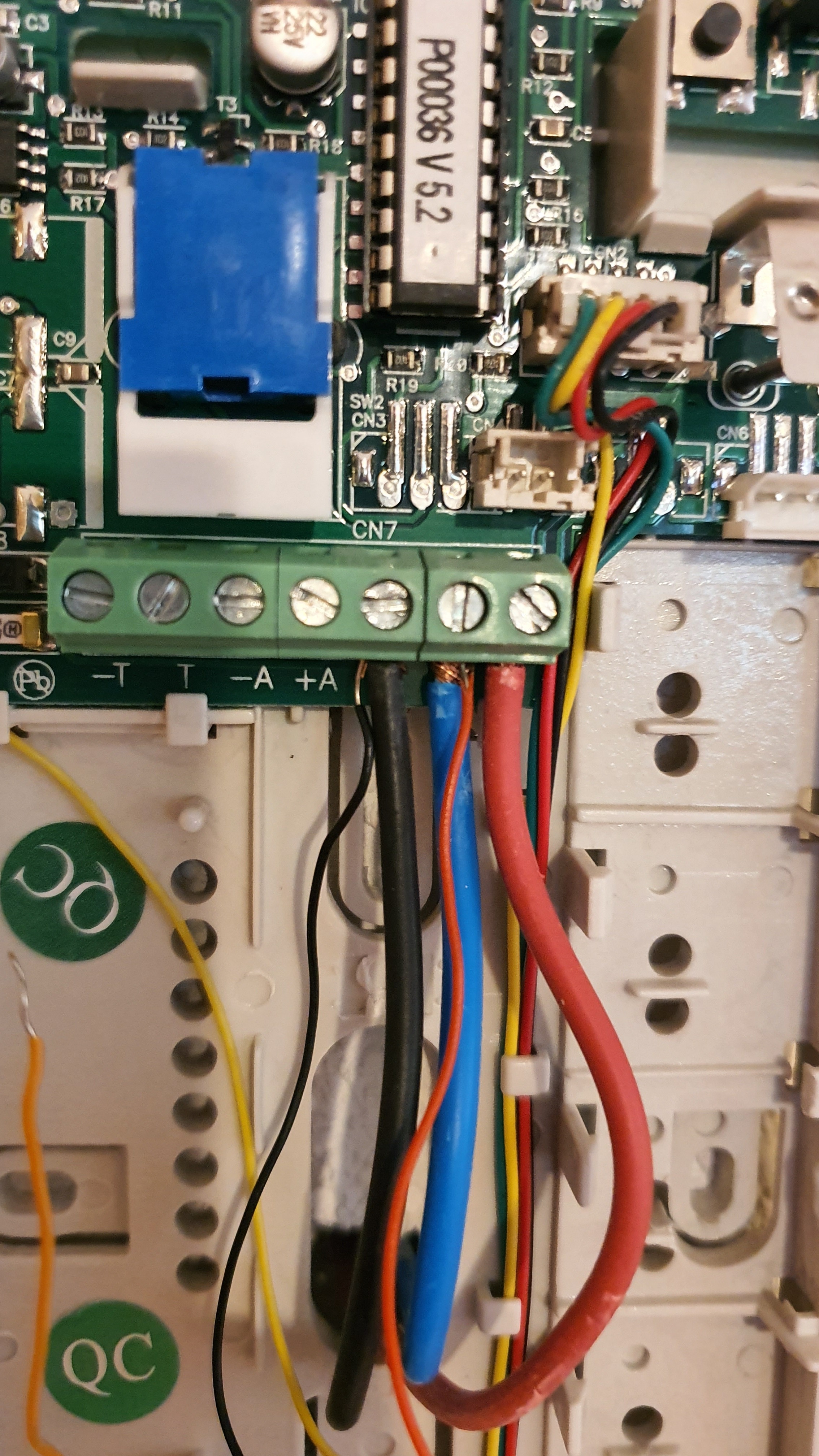
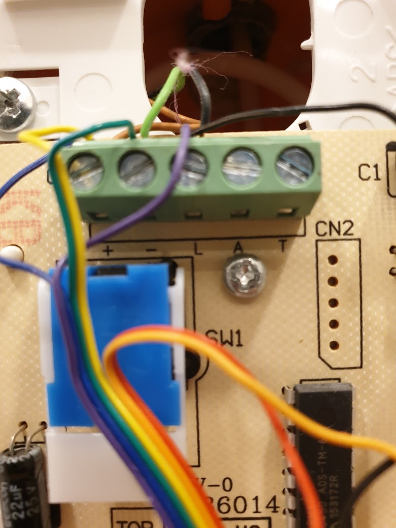
Blue one goes to the clamp with yellow from opener. Red, orange, green from opener to the old location of the blue one (L).
Black from opener to the black one.
Rerun setup.
Esa configuración es la que me indico George de nuki y no ha funcionado, lo que si está claro es que el L es el positivo del opener, detecta el timbrado y la apertura desde dentro, pero el opener no es capaz de abrir la puerta
Hi Manuel,
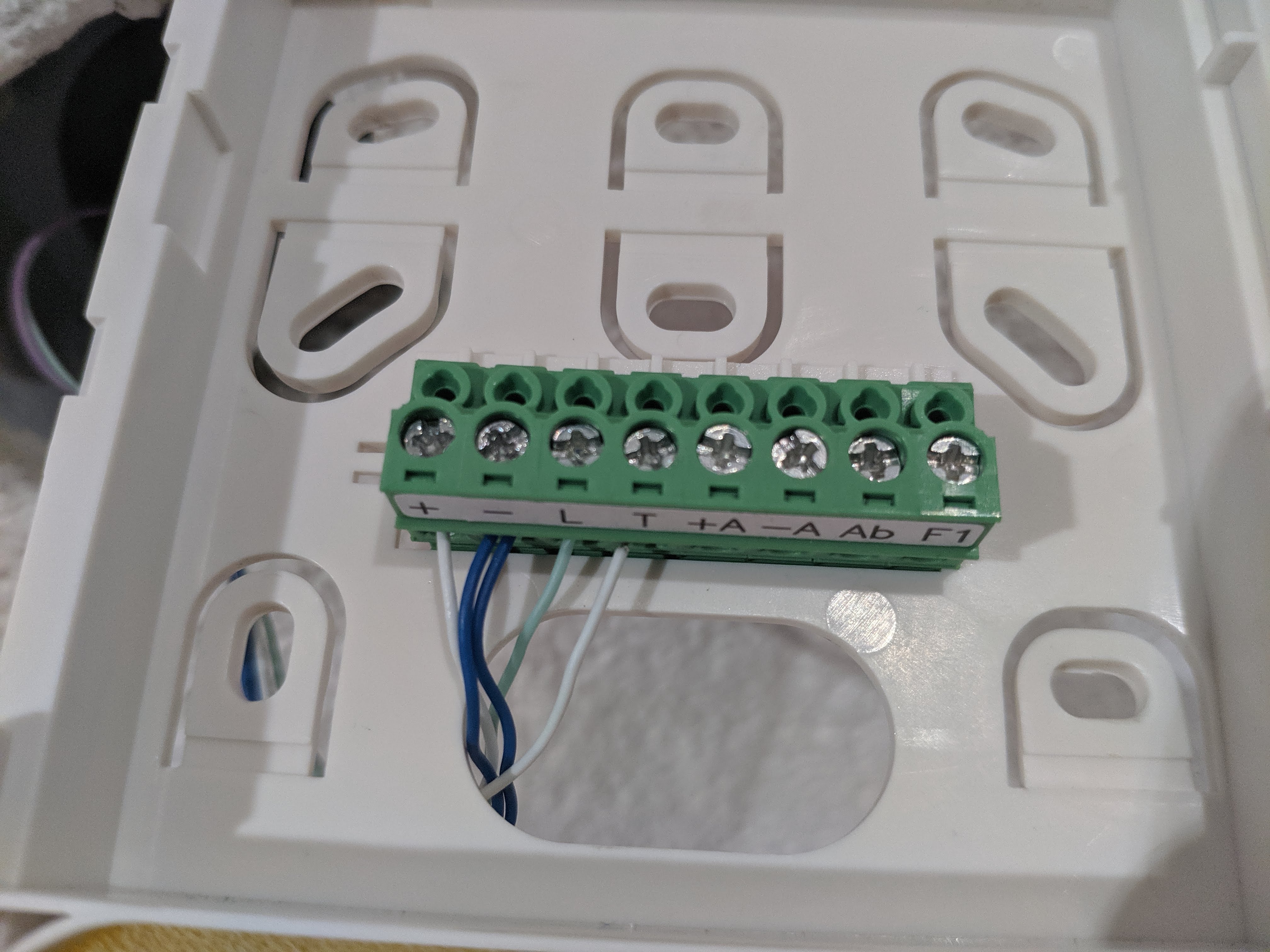
I also have the FERMAX 5601 and need support to connect it with the Opener.
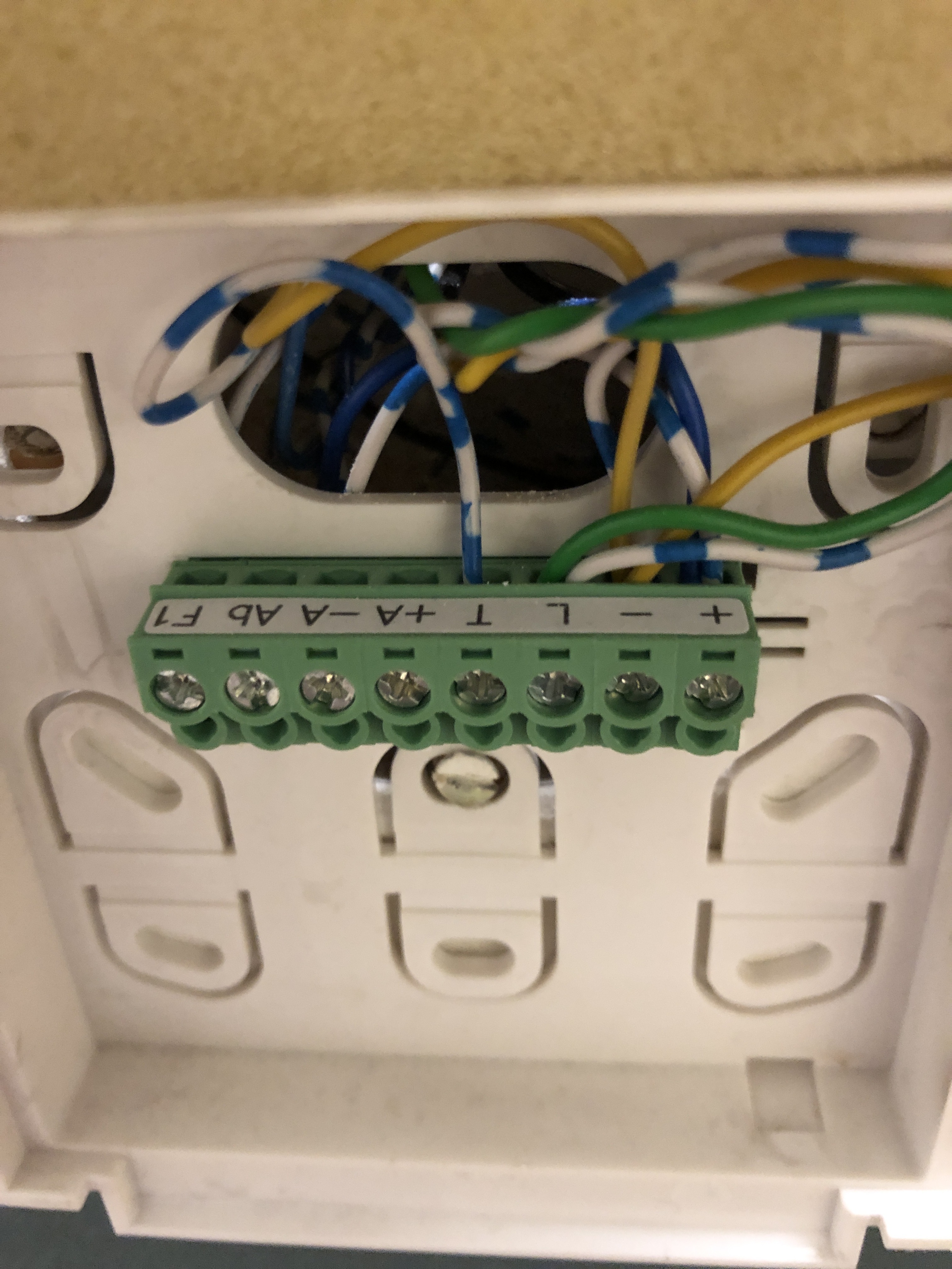
Can you please tell me, which cable colour from the opener connects to which FERMAX pin.
I have following cables connected to this pins:
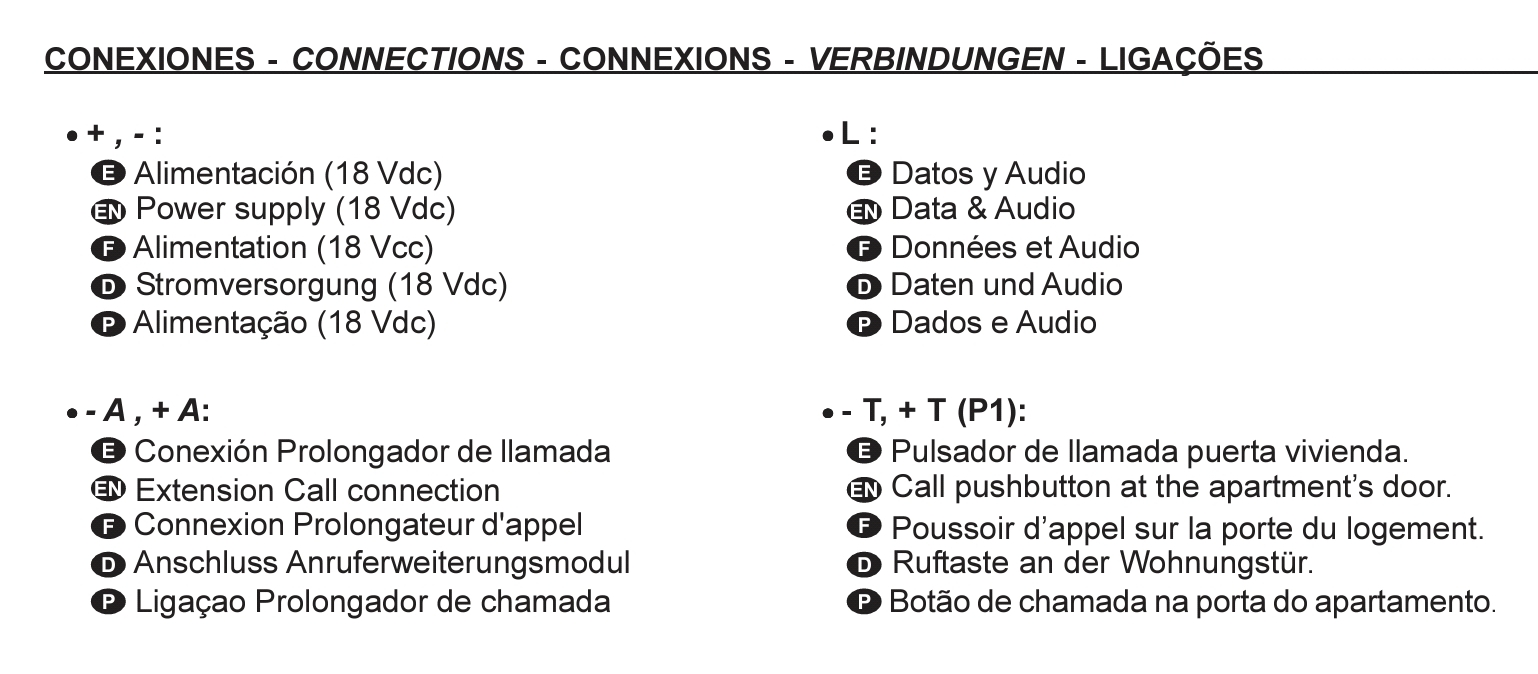
T:
L:
-:
+:
See:
Thank you very much for your support!
In your case unplug the 2 wires from intercom “L” and put on the Clamp. In the other Clamp, plug the yellow wire to Opener. Green, Orange and Red from the Opener to intercom “L”. And black from the Opener to intercom “-”.
Look if you need activation (need to call) from outside to open the door. Good luck.
THX for your fast response and support! I will try it when I am at home!
One more question: in the nuki app configuration I have to select a brand and model during the configuration from a selection list. Which product do I have to choose because my FERMAX 5601 is not listed.
THX
Generic Bus. Good Luck. The Fermax VDS is under investigation by Nuki so It can be fail like in my case.
Worked for you?. Thank you.
Any news of VDS test?. Thanks.
There are several threads about Fermax VDS already. Here’s the latest update:
Dear Community,
I want to share my experiences with the Nuki Opener and Fermax ADS with you.
I ordered the opener because according to the Nuki website the system “Fermax CityMax” is supported. Unfortunately this information is not completely correct, because - as it turned out - my CityMax is an ADS bus system. Specifically it is the indoor unit 60607 with the connection board 106CI08D.
I made the opener work, but with serious limitations, so I’m not sure yet if I will make use of my right of return.
Wiring: I chose the wiring variant for the generic bus without bell suppression. I connected the orange and the red wire of the opener with the data line of the bus (L) and the black wire of the opener with GND of the bus (-).
SW version: 1.2.7 (Opener)
Training: That was a bit tricky. Since I can only press the door open button after it has rung, but the Nuki app wants to record this signal first (@Nuki-Team: you should make it more flexible). Therefore I started the training mode only after I had established a connection between the indoor and outdoor units to start recording the opening signal. I couldn’t select in the app that my system only allows a door opening after a bell signal (@Nuki-Team: I was only offered this option as part of an error handling routine. I would have liked to have selected it before or changed it in the administration).
What works & what doesn’t:
Unlatch: Partly functional. If someone rang the bell, I can then open the door and don’t have to go to the indoor unit, but my main use case - I want to unlock the door for myself without ringing the bell - is not supported.
Ring-to-Open: This works, you should only set the maximum time very short. (see next point.)
Continuous mode: This mode works technically partially, but the function is not usable at all. The reason for this is that the opener reacts to all (!!!) bell signals of the entire house (!!!) and opens the door. This is an absolute no go and critical.
Nuki-App notifications: Here the same error strikes, I receive each time a notification if any (!) extension in the house is called. No go!
Nuki-Bridge API: The function to get callbacks when ringing is missing. This function is essential for me, because I want to run my solution autonomously without Nuki Web/Cloud.
Conclusion
I have partially made the opener work, but the solution is still far from ready for the market. Training the system was really hard, but the critical bug (Opener reacts to all extensions) and the missing feature (Bridge API, Ringing Callback) don’t make it easy for me to keep the Opener.