Hi Georg,
tried exactly as described (wiring and connection diagram), but unfortunately it still doesn’t work for me.
Here are the steps I did, maybe you can tell me if I made a mistake:
- firmware update Opener went well V 1.3.1
- reset Opener to factory settings in administration
- added Opener to my system configuration
- config asked me to connect to bridge - I did, connected, distance about 3-4 meters
- connected the 82 Ohm resistor to the blue cable
- connected wires like explained in the diagram
- connected Opener to the cabling
- started to configure Opener with Generic / Bus Golmar Plus (Beta)
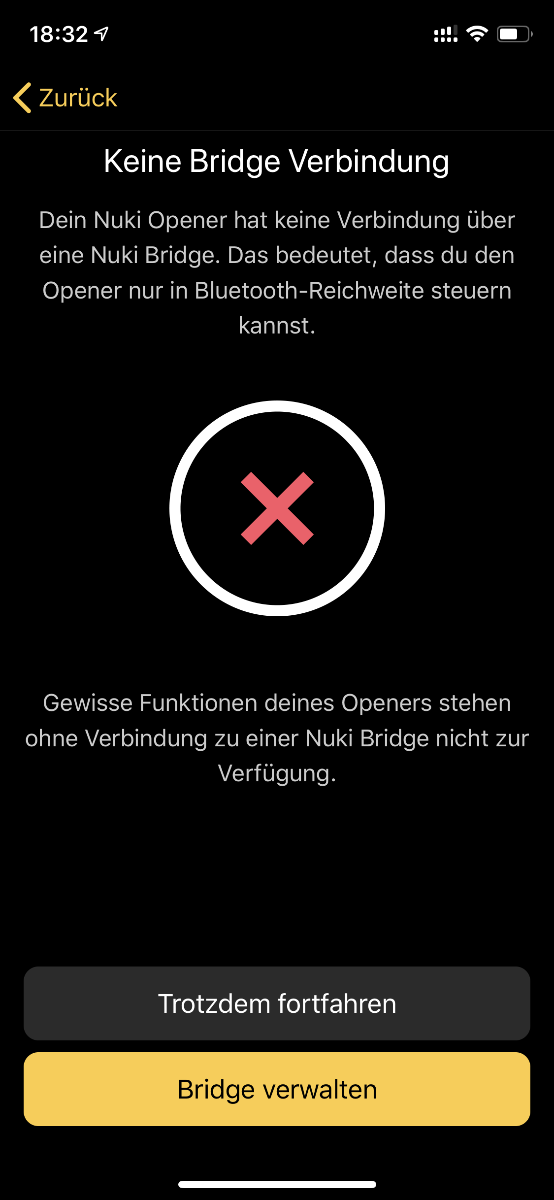
- got the following dialog after the initial steps and after the bridge was successfully connected (step 4)
- connected again to the bridge
- same issue again → LOOP here so I decided to continue anyway
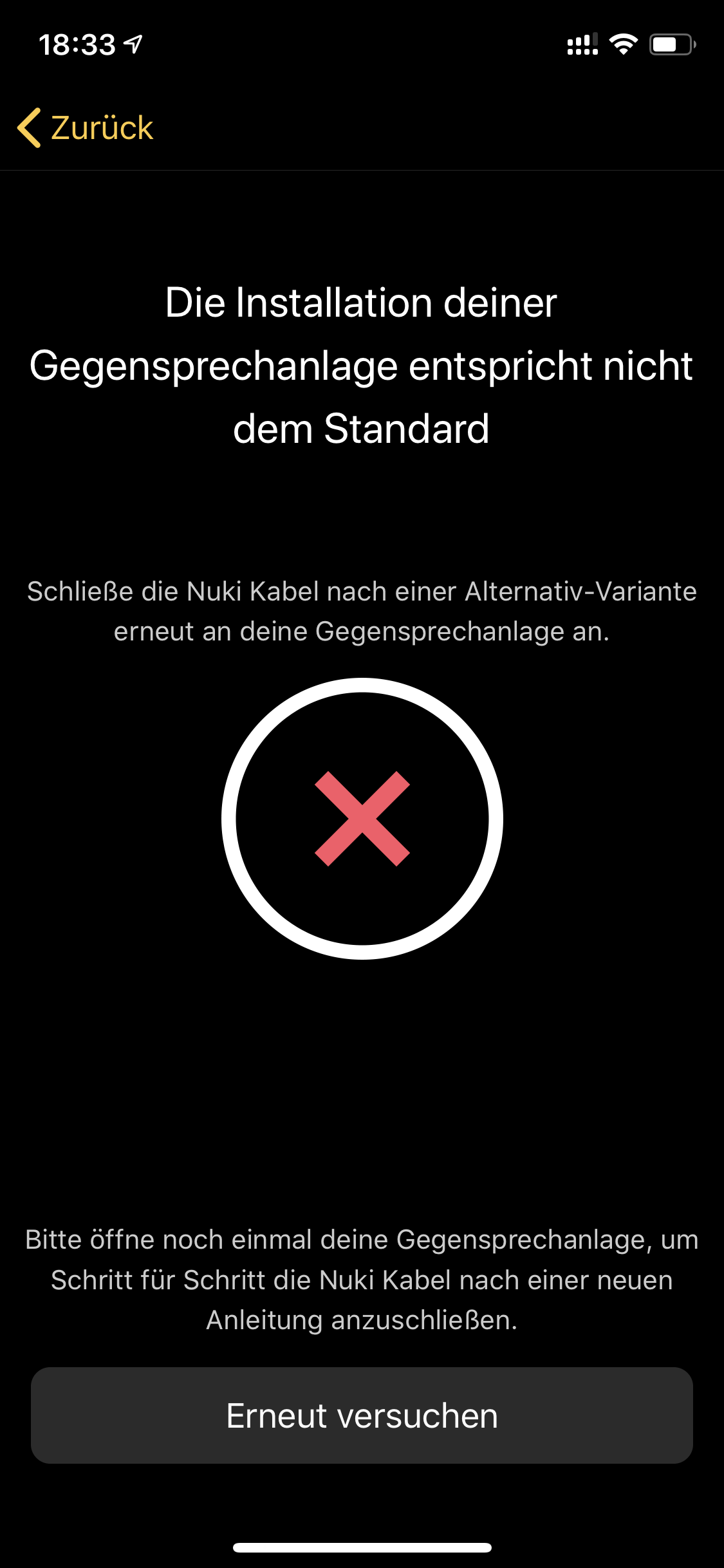
- now I got the following screen:
- tried again, same…
- tried other configuration types as show on the config screens (what about the yellow and red cable connection first ti (D) then on another try to (-) which does not fit to the wiring layout in the PDF…
I stopped here as it seem that either I am missing something or the configuration dialog does not realize the wiring as mentioned in the pdf file here: Golmar Plus intercom system support
Any help appreciated, as I would really love to have this working!
Thanks,
Chris