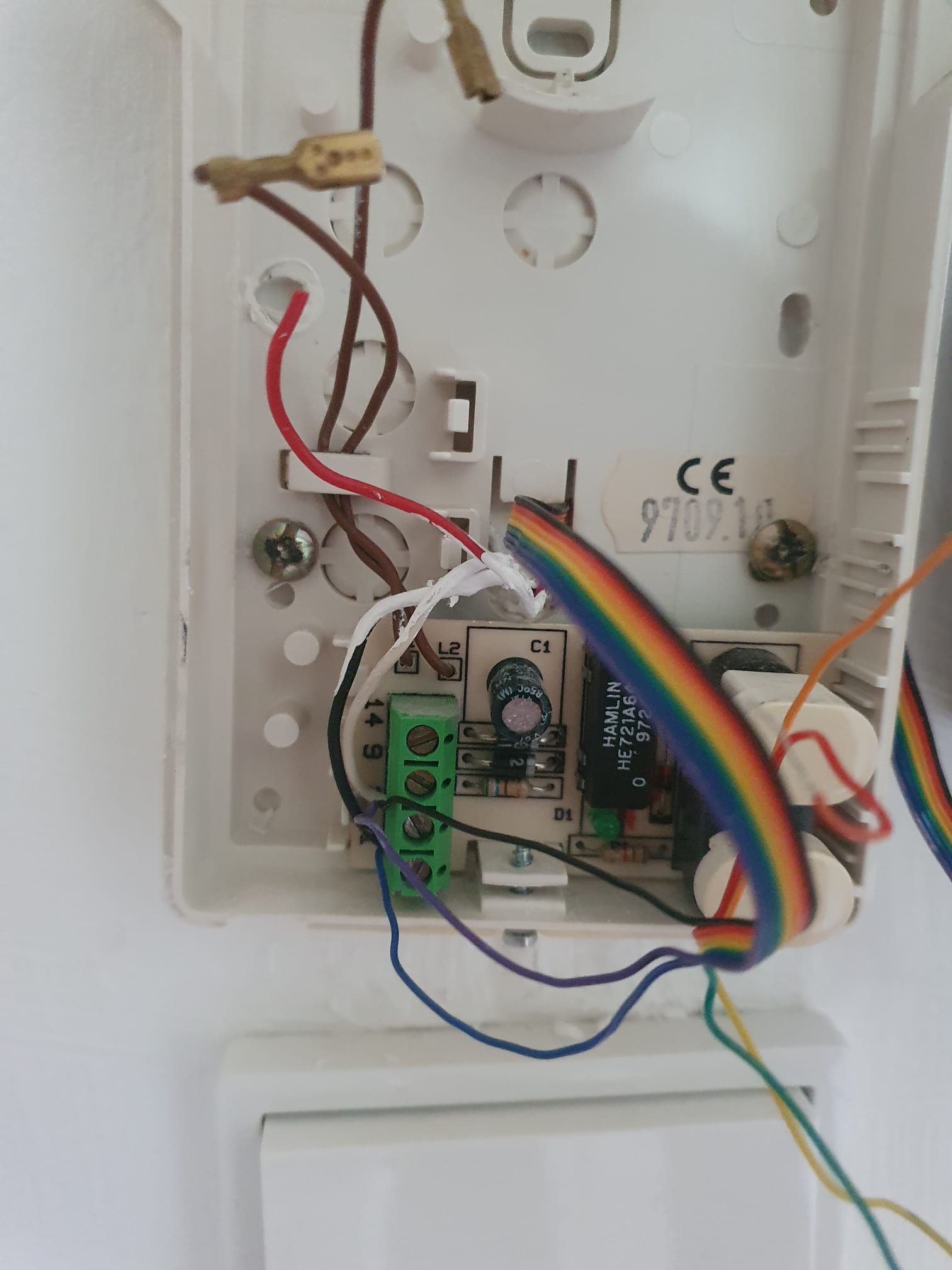
I have an old Ritto 6132 intercom. I managed so far to get to get the door to open, there are only two terminals connected (connect blue and violet.
I can’t get the ring detection to work properly though. As soon as I connect the bell and configure the opener, the door constantly opens, so I guess a ring is detected all the time.
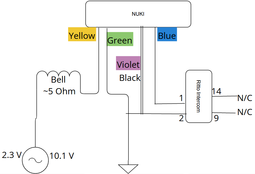
How I wired things: I connect black and violet to the ground of the opener. I checked and this ground is shared with the bell. So from what I read, I connected green to GND of the bell, and yellow back to bells now open terminal. I made a crude diagram for better understanding, see below.
I measured the voltage coming supplied to the bell (disconnected wires from the bell). Without ringing, I have a constant 2.3V AC. When I ring, there’s a short spike of 10.1V AC (shorter than the button press actually).
Is the constant 2.3V AC the problem here? Or any other ideas how to fix this?
Hi! I think you wired the external bell wrong, - was also a bit tricky as I had a external bell, and wanted to wire it to the opener! You need a cable with 2-wires what reaches from bell to opener, and two further 2-pole clamps (same as what comes with the opener), and then you have to unscrew the wire on “-” of the bell and connect it with one wire and clamps with the yellow opener wire, now connect the green opener wire over the second wire in the cable with clamp back to the “-” of the bell, finish! Explanation, ring signal goes to yellow opener wire through opener and with the green opener wire further to the bell! This should work! Let me know!
Hi and thanks for your answer. From what I understand I wired it the way you described it except yellow and green are the other way round. Maybe this isn’t clear from the diagram, but I’m running two wires from the bell to the opener; the bell is now chained with the opener.
So:
Bell GND goes to opener green
Yellow goes back to the previously disconnected terminal on the bell
I put it into the diagram like this because the ground of the bell and the intercom are the same - if I connect no wires I can measure full continuity between Bell GND and Ritto GND.
Ill retry with green and yellow swapped - are you sure about this? So far I always read it the other way round.
Hi! Yes is sometimes a issue, but you can solve it, with a pull-down-resistor! Is done often, and usually works! For analogue systems, this is the wiring configuration of the opener, - blue(opening)&purple(gnd1), black(gnd2), yellow(bell signal into opener)&green(bell signal out of opener), red&orange(Voice-In/Out, but is not in use yet), - for digital systems, the wiring configuration depends on the system.
Ok, I made a somewhat fundamental error, I confused polarity. Also the system seems to be 24V DC, not AC, I’ve rewired everything and it works kind of better now. Instead of constant opening, it only happens after a few seconds.
So I think the pull-down resistor could work. I’m not a 100% sure where to put it. I pull the input (yellow wire) to ground?
Ah I see. And yes correct, you pull the input (yellow) down, - just do the resistor between the screw on the bell and the wire what is now connect to it, and is going to the yellow opener wire. When you choose the right value for the resistor, it holds the voltage down, and gives the power through just when someone rings, and the voltage rising up with it, what just overreaching the resistor value, what let then the voltage through, and the opener detects it.
No luck - I went down as far as 660 Ohms, the opener insists on detecting a signal without ringing the door. It takes about ~20 seconds after activationg RTO and you hear the buzzer downstairs. Thanks nevertheless - worst case I can use it only for opening the door.
Hmm…
And you are sure you use the “-” screw of the bell, because I had the same issue, when I tried to use screw “+” of the bell, and as I changed to “-” it was solved.
I have tried all possible permutations to connect the wires, it only changes how often a ring without a ring is detected. What’s strange is that the intercom works on 24V DC and the bell on ~10V AC (possibly it’s actually a 12V AC system), yet the + of both systems seem to be directly connected.
I’ve ordered an AC Relais now. Connecting the yellow wire to the +24V DC makes it detect a ring (no green wire necessary). I’ll just have the bell triggering the relais which connects the yellow wire with 24V. Fortunately I already have my own ring suppression via an arduino and a relais, so there’s no disadvantage from this solution.
I can report success on the relais solution. For reference, I used a “Finder 40.52.8.012.0000” relais. A smaller version of this relais should also do, but that’s what was available on Amazon at the time.