Hi all,
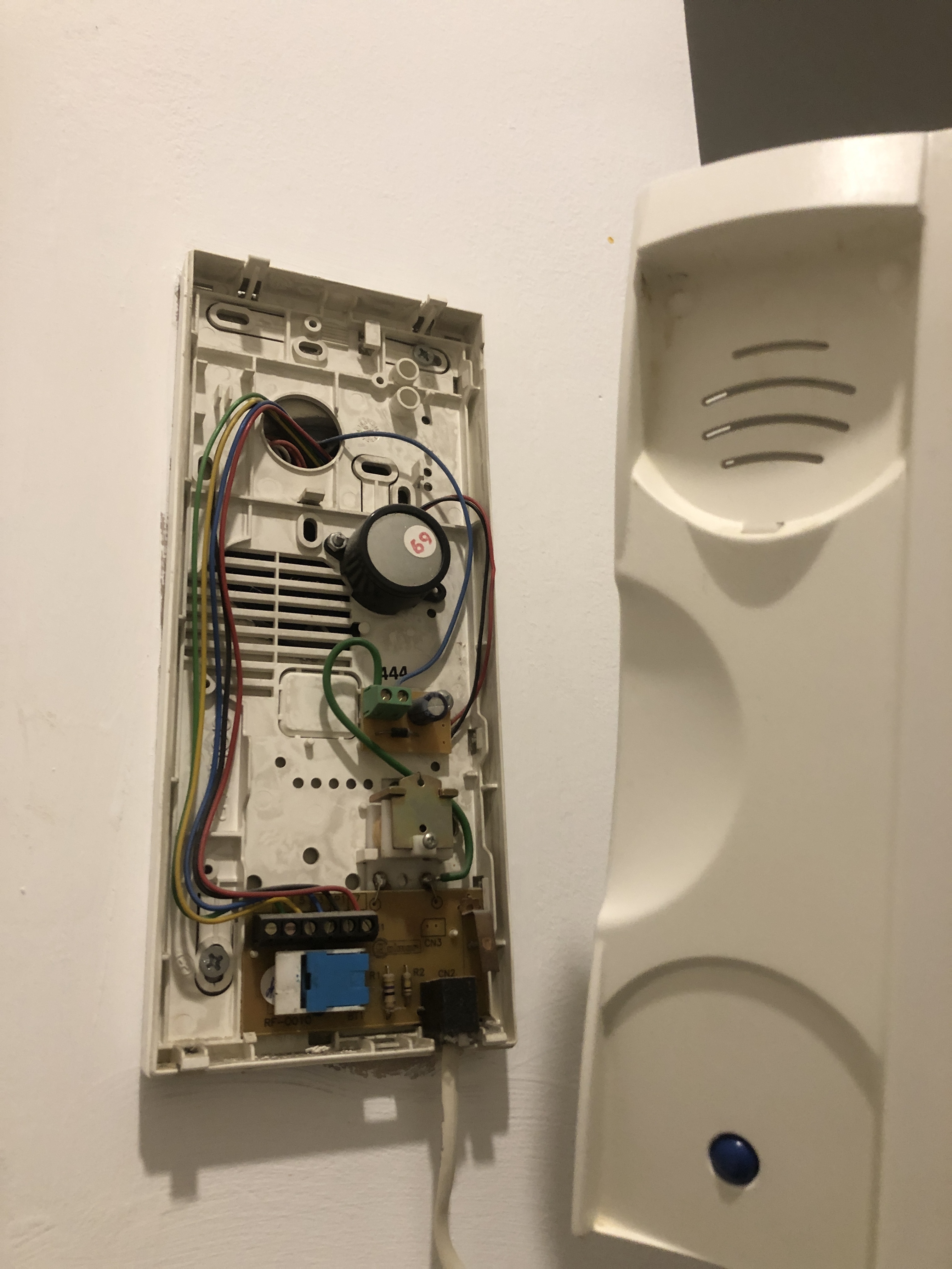
Did anyone make the opener work with the Golmar RF-0010 system? I couldn’t even determine whether it was a bus or analogue system, as described in the ‘unknown systems manual’.
Really hope that someone has tried this already ![]()
Hi all,
Did anyone make the opener work with the Golmar RF-0010 system? I couldn’t even determine whether it was a bus or analogue system, as described in the ‘unknown systems manual’.
Really hope that someone has tried this already ![]()
Hey,
Did you get any luck so far?! ![]()
I’m afraid not ![]()
Thanks for the reply. I suppose you also live in the Netherlands? Buying another device (maybe a newer one) and using the existing wires would be a solution you think?
I recently bought the Nuki Opener and just got it connected with the Golmar RF-0010. This is clearly an analog system as it is old and has a lot of wires.
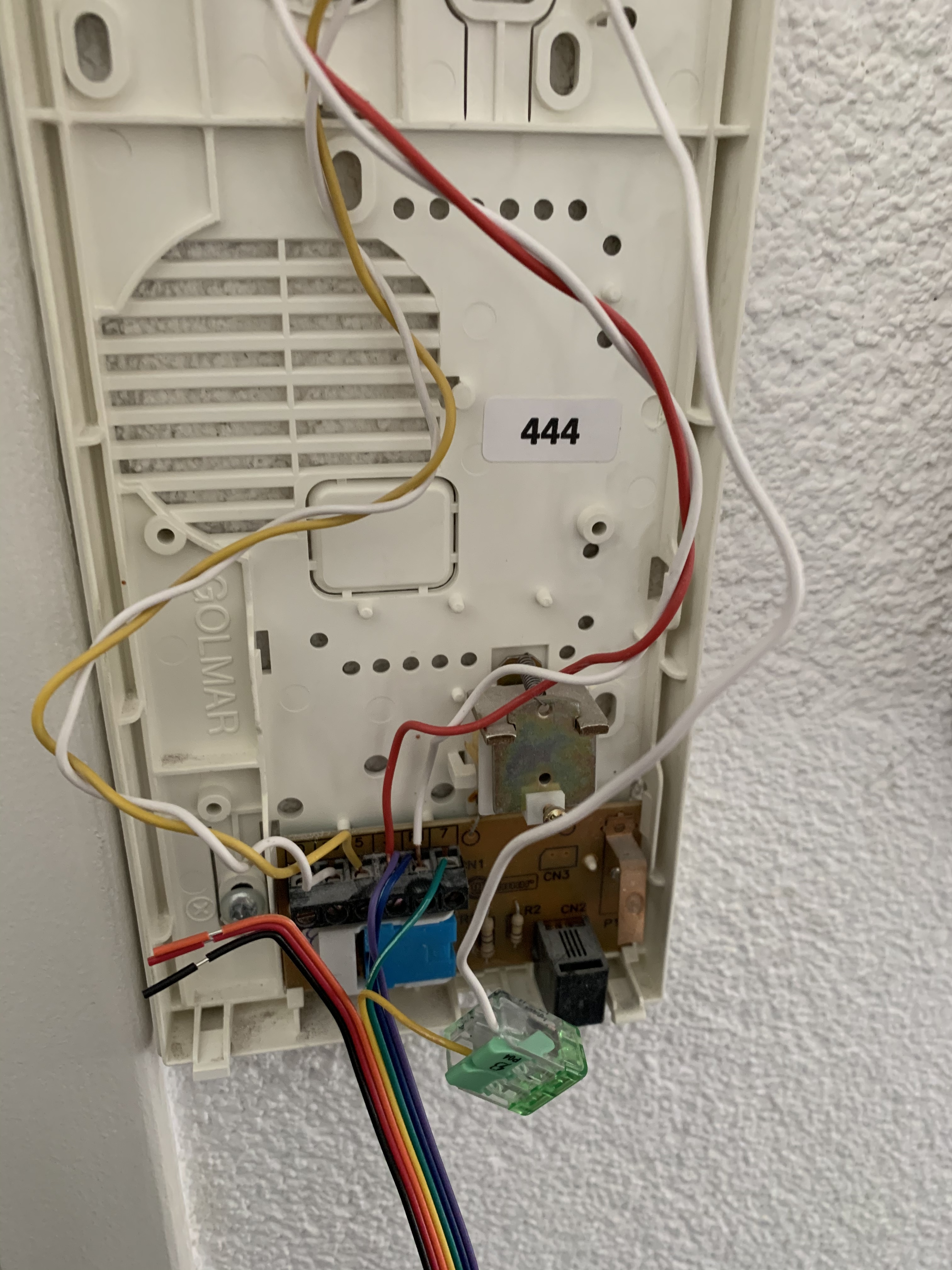
I set up the Golmar RF-0010 like this:
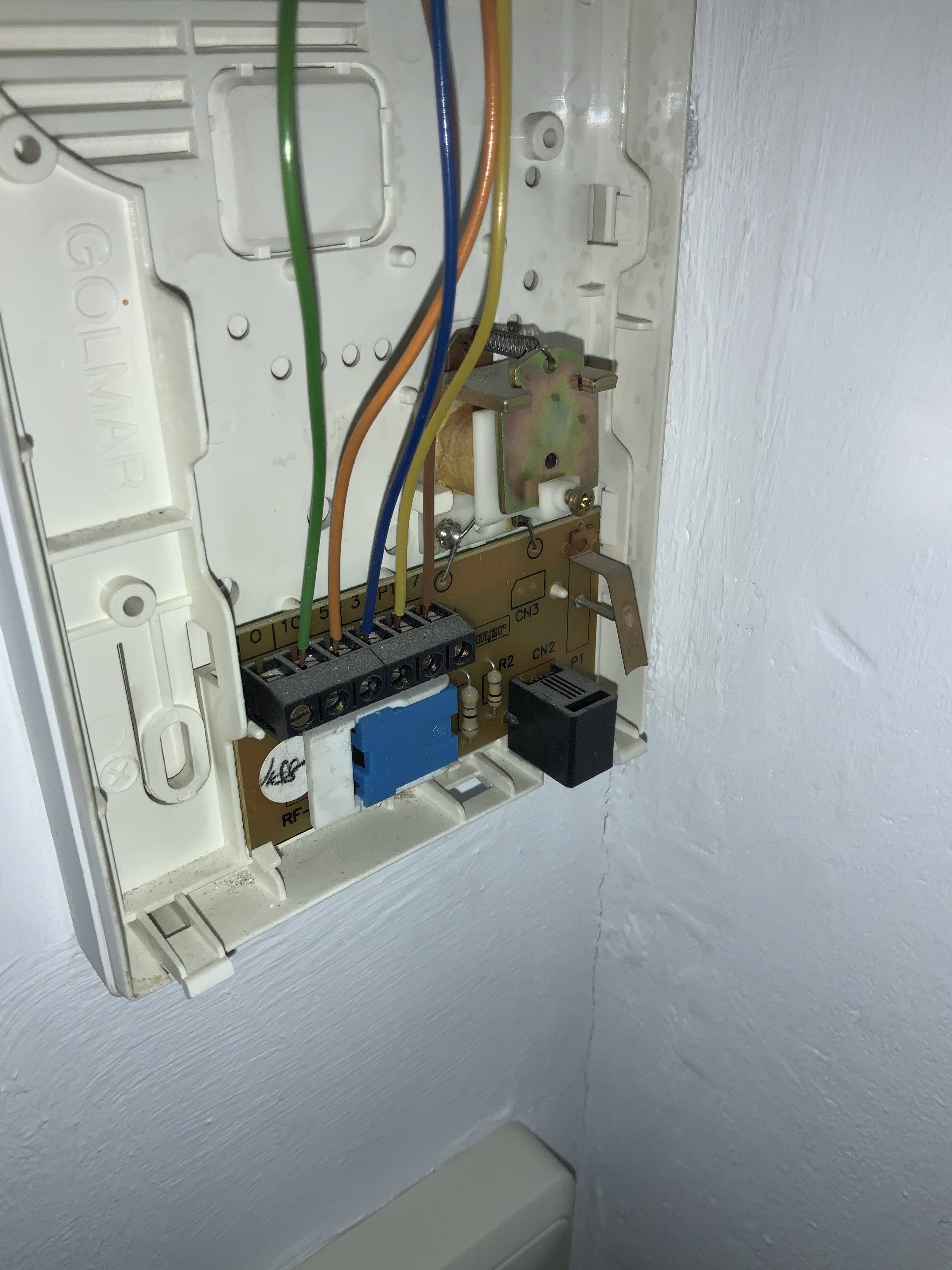
The Golmar has on the board the following numbers:
0, 10, 5, 3, P1, 7
Purple is connected to 3
Blue is connected to P1
Green is connected with 7
The cable that was in 7 is connected with the yellow cable.
With this setup everything is working fine for me.
I did not use the cables in 10 and 5 and 0 is empty. 10, 5 and 0 are probably used for talking which is not working on my intercom.
@PatrickSindelka Thanks for sharing. Sounds interesting. I use my intercom for talking so I want to make sure it is all going to work before I buy anything.
You happen to have a picture?
Still hoping for more suggestions or examples of how to upgrade my existing system without interfering with the intercomsystem of the while complex.
See hereby a picture, I wasn’t allowed to upload them earlier as it was my first post.
@Hanna_Jaap_Rusticus I only connected cables that are not related to talking. The system is analog so it should have no impact on talking. All cables except the ring cable are still in the intercom as before, Nuki is just added as an extra connected cable.
But I did not connect the Nuki bridge to the talking cables (Microphone and Speaker cable) as I do not know which one is for what. And in the current firmware the Nuki bridge does not use them anyways, they are just there for future updates.
HELLO GUYS… hello Patrick… any news about the GOLMAR RF-0010 ??
By some reason, I set it up as you mentioned, but it is working partially.
First… I followed your connection schema : The Golmar has on the board the following numbers:
0, 10, 5, 3, P1, 7
Purple is connected to 3
Blue is connected to P1
Green is connected with 7
The cable that was in 7 is connected with the yellow cable.
While setting up the Opener, in the frist step of the setup, the APP , YES IT DOES opens the door, but … the second step fails ( the one that when the Main Downstairs Doorbell is pressed, but the Opener DOES NOT open the door )
Any thoughts ? any other model we can replace ? ( there are many combination on the configuration list in the Nuli App and I dont know which one to try )
WOuld appreciate advise…
What you can try is play around with the cable that was in 7. If there is no cable in 7, the doorbell should not ring. That way you can verifiy that in your case 7 is also used for the doorbell.
Hi! When you have an external bell, there goes no ring signal to the intercom, and you have then to wire the “-” screw of the bell directly to the opener, for the ring detection and ring functions! Let me know, if you need help with it!
Hi Max, did you find any solution with golmar RF-0010? Or do you know of a model for which it can be successfully replaced.
I have a RF-0010 and I have tried to connect it as Patrick Sindelca indicates but it doesn’t work.
I would really appreciate your help or that of someone who has found a solution.
Thanks in advance.
I recently installed a Nuki Opener system to a Golmar RF-0010 intercom, which I believe is a T-910 model. I’d like to share my process and some insights that might help others looking to do the same.
Step-by-Step Guide to Identify Wires and Install Nuki Opener
Identify Each Wire:
• Tools Needed: Multimeter
• Process: Initially, I was not sure about the function of each wire. I used a multimeter to measure voltage changes as the intercom was used (e.g., during ringing and speaking). This helped pinpoint the function based on the voltage fluctuation.
Testing Wire Functionality:
• Method: I disconnected one wire at a time to observe which functionality was lost. This trial-and-error method was crucial for correctly identifying each wire.
• Findings:
• Wire 0: Ringer
• Wire 10: Speaker
• Wire 5: Microphone
• Wire 3: Minus (Common wire, removing this caused all functions to stop)
• Wire P1: Door opener button
• Wire 7: Ground (No ground was installed, verified as ground through multimeter)
Installation:
• After identifying the wires, I connected them to the Nuki Opener using Generic Analog installation setup. - Make sure to follow the Nuki installation guide closely to connect the correct wires to their respective terminals in the Nuki system.
Final Setup and Testing:
• Once all connections were made, I tested the functionality:
• Ring to Open: Worked as expected.
• General Operation: Checked that all intercom functionalities were operational with the Nuki system in place.
Wire Connections:
Unfortunately, I forgot to take a picture of the installation, but here’s how the wires should be connected based on their colors:
• Yellow to 0: Ringer
• Blue to P1: Door opener button
• Purple and Black to 7: Ground
• Red to 10: Speaker
• Orange to 5: Microphone
This method should work well for any analog intercom system as it mainly relies on understanding and testing the wire functions rather than specific wire color coding or pre-determined wiring schemas.